Mounting the Parallel Plate Ball Bearing Protection
|
Step |
Action |
|---|---|
|
1 |
Remove the telescopic axis as described in Replacing the Telescopic Axis. |
|
2 |
Remove the lower arms as described in Replacing the Lower Arms. |
|
3 |
Slide the cover top side (1) over the lower universal joint (2) of the telescopic axis and then attach the parallel plate (3) to the universal joint by using the three countersunk screws that were removed previously. Use the high strength retaining compound Loctite 648 for this purpose. Tightening torque: 1 Nm (8.9 lbf-in) 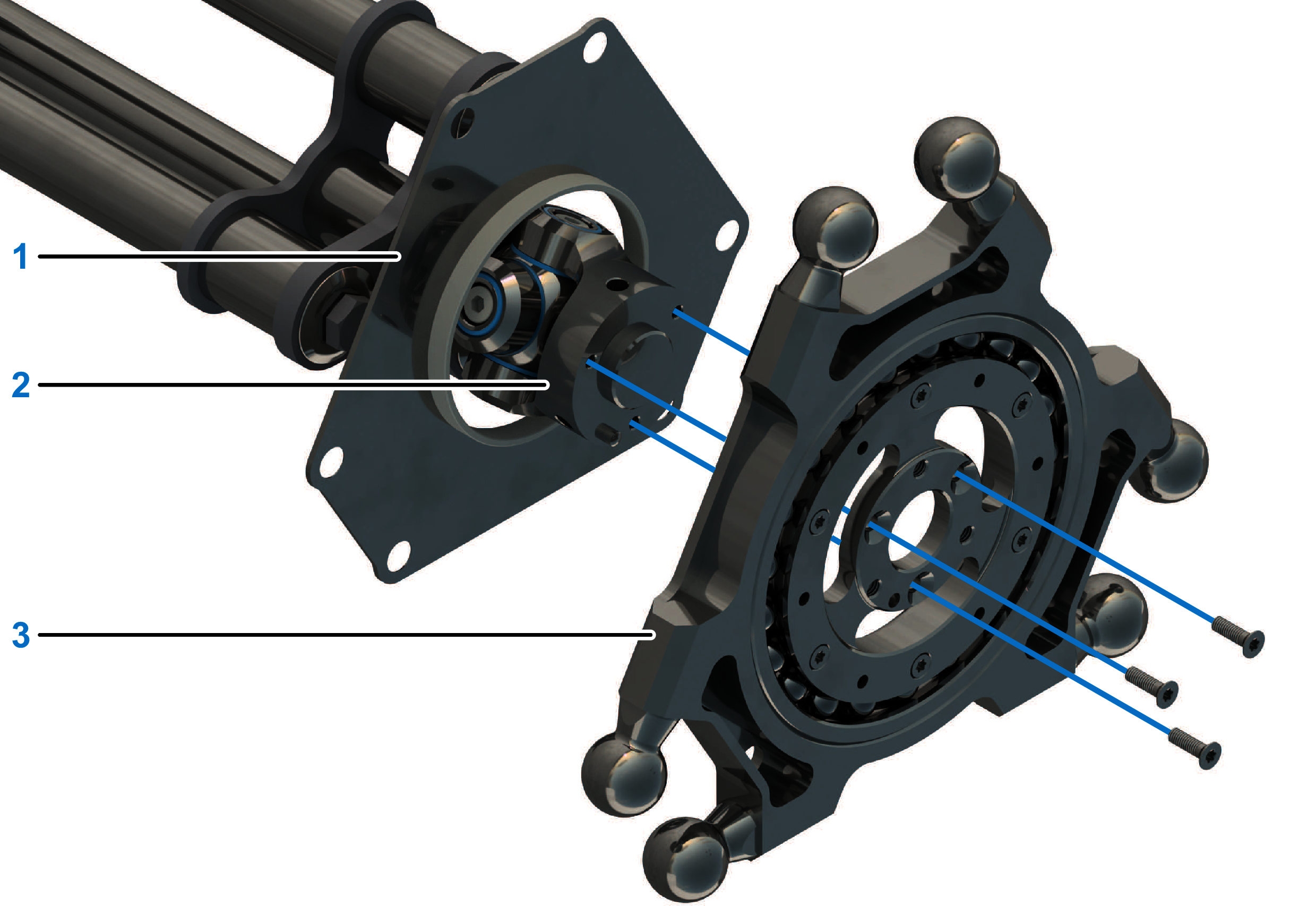
NOTE: Apply the high strength retaining compound Loctite 648 into the tapped holes as opposed to applying it to the screws.
|
|
4 |
Fasten the flange offset ring (4) to the parallel plate with the three counter sunk screws M4x10 (6) and six counter sunk screws M2.5x16 (5). Use the medium strength threadlocking adhesive Loctite 243 for this purpose. Tightening torque:
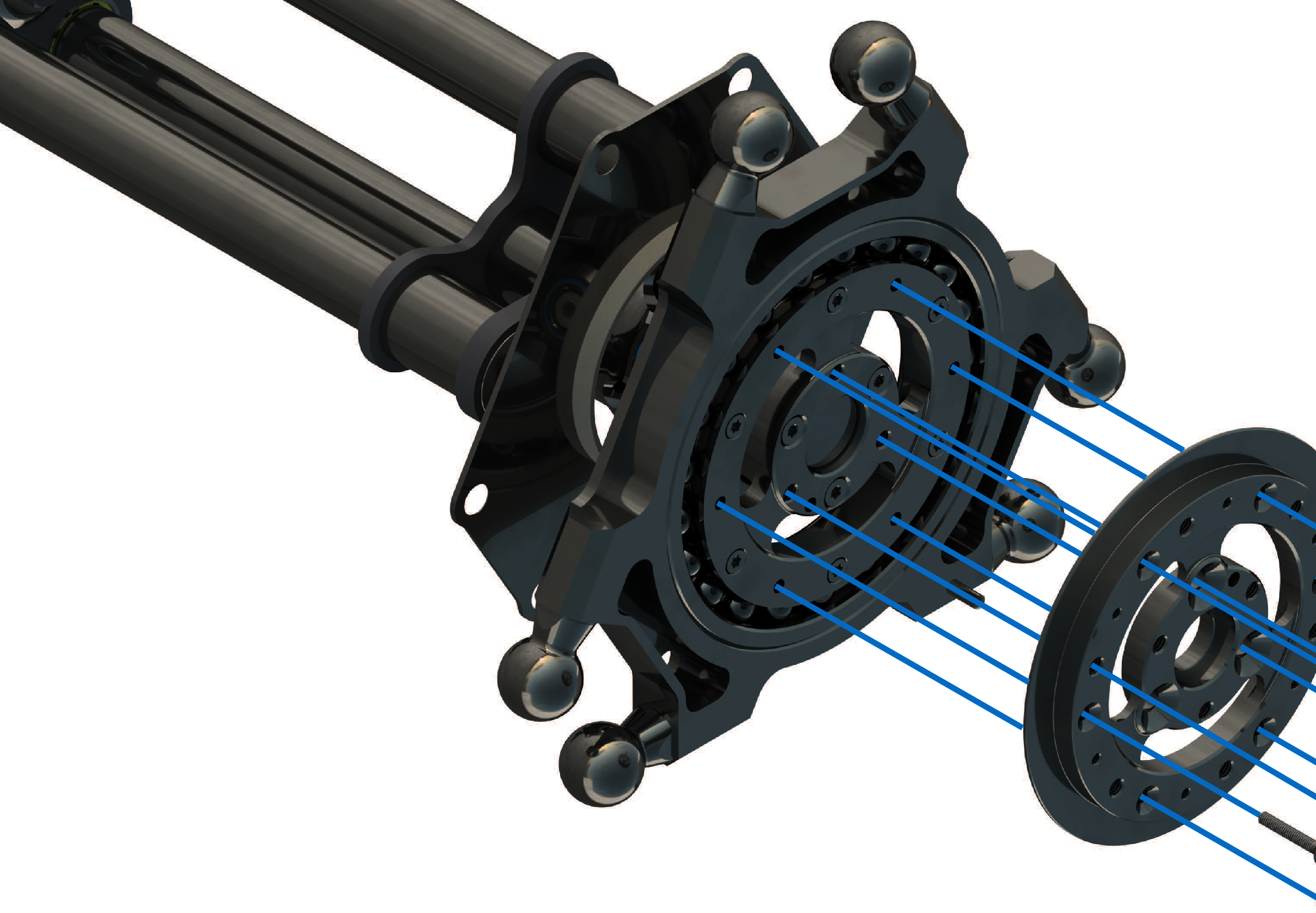
NOTE: Apply the medium strength threadlocking adhesive Loctite 243 into the tapped holes as opposed to applying it to the screws.
|
|
5 |
Insert the collar nuts (7) from above through the top cover and the six bores Ø6.4 of the parallel plate. 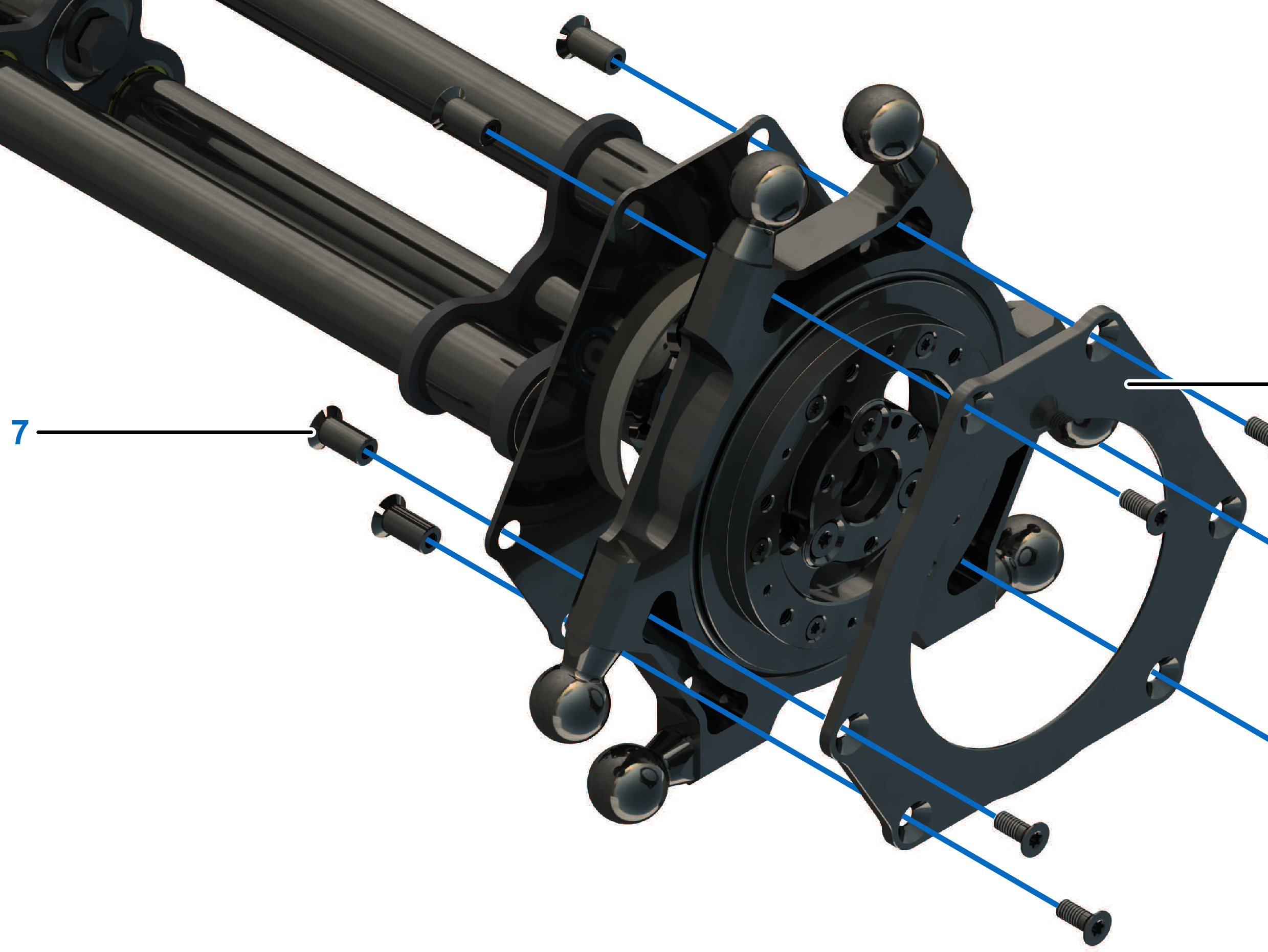
|
|
6 |
Fasten the bottom cover (8) to the parallel plate with the six counter sunk screws M4x10 (9) and the collar nuts. Use the medium strength threadlocking adhesive Loctite 243 for this purpose. Tightening torque: 1.8 Nm (15.9 lbf-in)
NOTE: Apply the medium strength threadlocking adhesive Loctite 243 into the tapped holes as opposed to applying it to the screws.
|
|
7 |
Check the ball bearing for ease of movement and grinding noises by rotating the parallel plate. 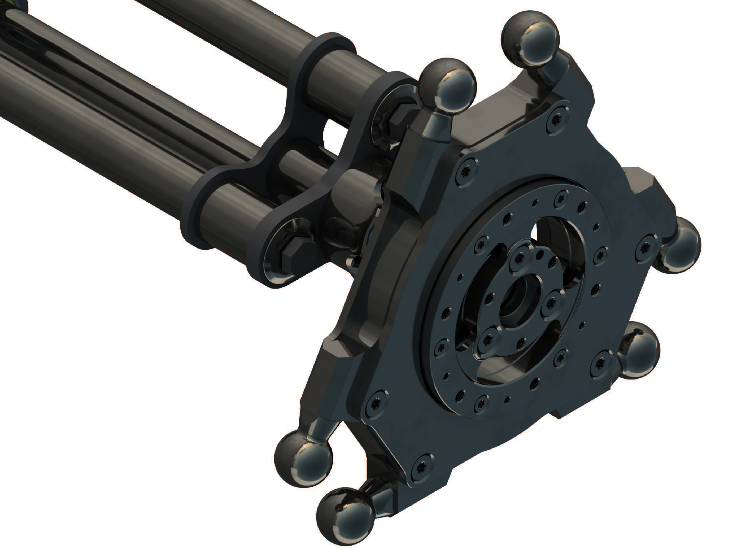
NOTE: The ball bearings should turn smoothly. There should be no grinding noises.
|
|
8 |
Mount the telescopic axis and the lower arms. For further information, refer to Replacing the Telescopic Axis and Replacing the Lower Arms. |