Additional signal sequence diagram
Temporary intermediate states are not illustrated in the signal sequence diagram. Only typical input signal combinations are illustrated in the diagram. Other signal combinations are possible.
The most significant areas within the signal sequence diagram are highlighted in color.
Refer also to the diagram found in the overview for this function block.
The signal sequence diagrams in this documentation possibly omit particular diagnostic codes. For example, a diagnostic code is possibly not shown if the related function block state is a temporary transition state and only active for one cycle of the Safety Logic Controller.
Only typical input signal combinations are illustrated. Other signal combinations are possible.
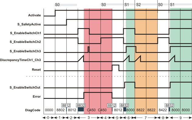
Restart inhibit after equivalence error (S_AutoReset = SAFEFALSE)
|
0 |
The function block is not yet activated (Activate = FALSE). As a result, all outputs are FALSE or SAFEFALSE. |
|
1 |
The function block is activated (Activate = TRUE). Switching stage 0 (S0 in the figure) is present (input S_EnableSwitchCh1 and S_EnableSwitchCh3 = SAFEFALSE, input S_EnableSwitchCh2 = SAFETRUE). The operating mode is not active (S_SafetyActive = SAFEFALSE). The S_EnableSwitchOut output remains in the defined safe state (SAFEFALSE). |
|
2 |
The operating mode is signaled via the feedback signal S_SafetyActive = SAFETRUE. |
|
3 |
The change from switching stage 0 to switching stage 1 fails: S_EnableSwitchCh1 switches to SAFETRUE and S_EnableSwitchCh2 becomes SAFEFALSE. S_EnableSwitchCh3, however, does not follow the signal at input S_EnableSwitchCh1 within the time period set at DiscrepancyTimeCh1_Ch3. The relevant conditions for enabling are not fulfilled. S_EnableSwitchOut output remains SAFEFALSE. The Error output becomes TRUE to indicate the error state. |
|
4 |
The defective enable switch device is replaced. During replacement, SAFEFALSE applies to the inputs S_EnableSwitchCh1 to S_EnableSwitchCh3. With the new enable switch device connected, switching stage 0 (S0 in the figure) is present again. As no reset has yet been performed, the Error output remains TRUE and S_EnableSwitchOut output remains SAFEFALSE. |
|
5 |
As the error reason does no longer exist, the positive edge at the Reset input resets the Error output to FALSE and removes the restart inhibit. According to switching state 0, S_EnableSwitchOut remains SAFEFALSE. |
|
6 |
Change from switching stage 0 to switching stage 1 (S1 in the figure): S_EnableSwitchCh1 switches to SAFETRUE and S_EnableSwitchCh2 becomes SAFEFALSE. S_EnableSwitchCh3 follows S_EnableSwitchCh1 within the time period set at DiscrepancyTimeCh1_Ch3. All relevant conditions are fulfilled, S_EnableSwitchOut output becomes SAFETRUE. |
|
7 |
Change from switching stage 1 to switching stage 2 (S_EnableSwitchCh1 and S_EnableSwitchCh2 and S_EnableSwitchCh3 = SAFEFALSE), the S_EnableSwitchOut output becomes SAFEFALSE. |
|
8 |
From stage 2 a transition is only possible to stage 0: By releasing the button of the enable switch device, input S_EnableSwitchCh1 and S_EnableSwitchCh3 switch to SAFEFALSE (DiscrepancyTimeCh1_Ch3 is not exceeded) and input S_EnableSwitchCh2 becomes SAFETRUE. S_EnableSwitchOut output remains SAFEFALSE. |
|
9 |
Successful change from switching stage 0 to switching stage 1 (S1 in the figure). All relevant conditions are fulfilled, S_EnableSwitchOut output becomes SAFETRUE. |