Operation Mode
Overview
Refer to the Smart Template Modules User Guide for more information on displaying the different tabs.
The tab provides a tab for each operation mode on the left-hand side:
On the right-hand side, the tab displays a visualization of the robot. The visualization can be configured ( and ).
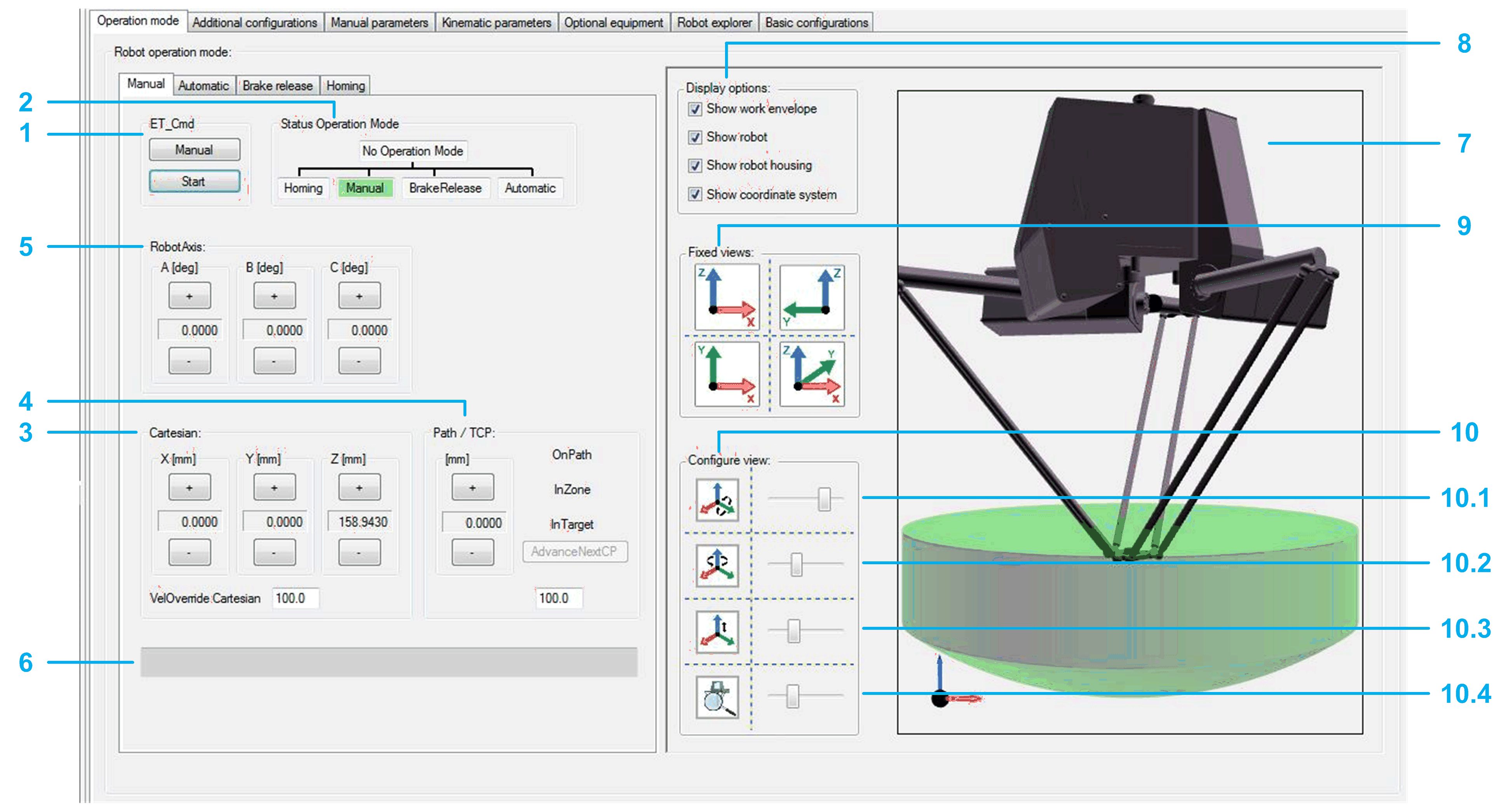
Manual Tab
-
The left-hand side of the tab helps you to move the robot manually.
-
The right-hand side of the tab displays the robot movements in a 3D visualization. The visualization can be configured ( and ).
| WARNING | |
|---|---|

Moving the robot manually:
|
1 |
If the module is not in the operation mode , click the button to send the command RM.ET_Cmd.Manual, and then click the button to send the command RM.ET_Cmd.Start. If the operation mode is accepted, the background color of the operation mode status switches to green. |
|
2 |
Displays the operation mode of the module. If the robot is in operation mode, you can move the robot step-by-step with the buttons of the various jogging modes:
|
|
3 |
Click the buttons (positive / negative) to move (jog) the TCP (Tool Center Point) along the axes of the Cartesian coordinate system. The displayed cartesian parameters depend on the configuration of ET_WorkingPlane (refer to Robotic Library Guide). : Proportional influence of the active Cartesian jogging velocity. Unit: % |
|
4 |
Click the buttons (positive / negative) to move (jog) the TCP (Tool Center Point) along a connected path (if a connected path is available). For status information on the TCP movement, refer to the feedback properties xOnPath, xInZone, and xInTarget (refer to Robotic Library Guide). : Proportional influence of the active path jogging velocity. Unit: %. |
|
5 |
Click the buttons (positive / negative) to move (jog) along the robot axes by controlling the corresponding drives. |
|
6 |
Displays the pending hardware and software limits. |
Configuring the visualization:
|
7 |
Shows the movement of the robot, particularly the TCP (Tool Center Point) movement within the working plane. |
|
8 |
Activate the check boxes to define what is displayed in the (work envelope, robot, robot housing, coordinate system). |
|
9 |
Click one of the four buttons to select a fixed default view of the robot. |
|
10 |
Move the sliders to configure the rotation, translation, and zoom of the displayed robot. 10.1 Rotation around Y-axis 10.2 Rotation around Z-axis 10.3 Translation in direction of Z-axis 10.4 Zoom |
Automatic Tab
-
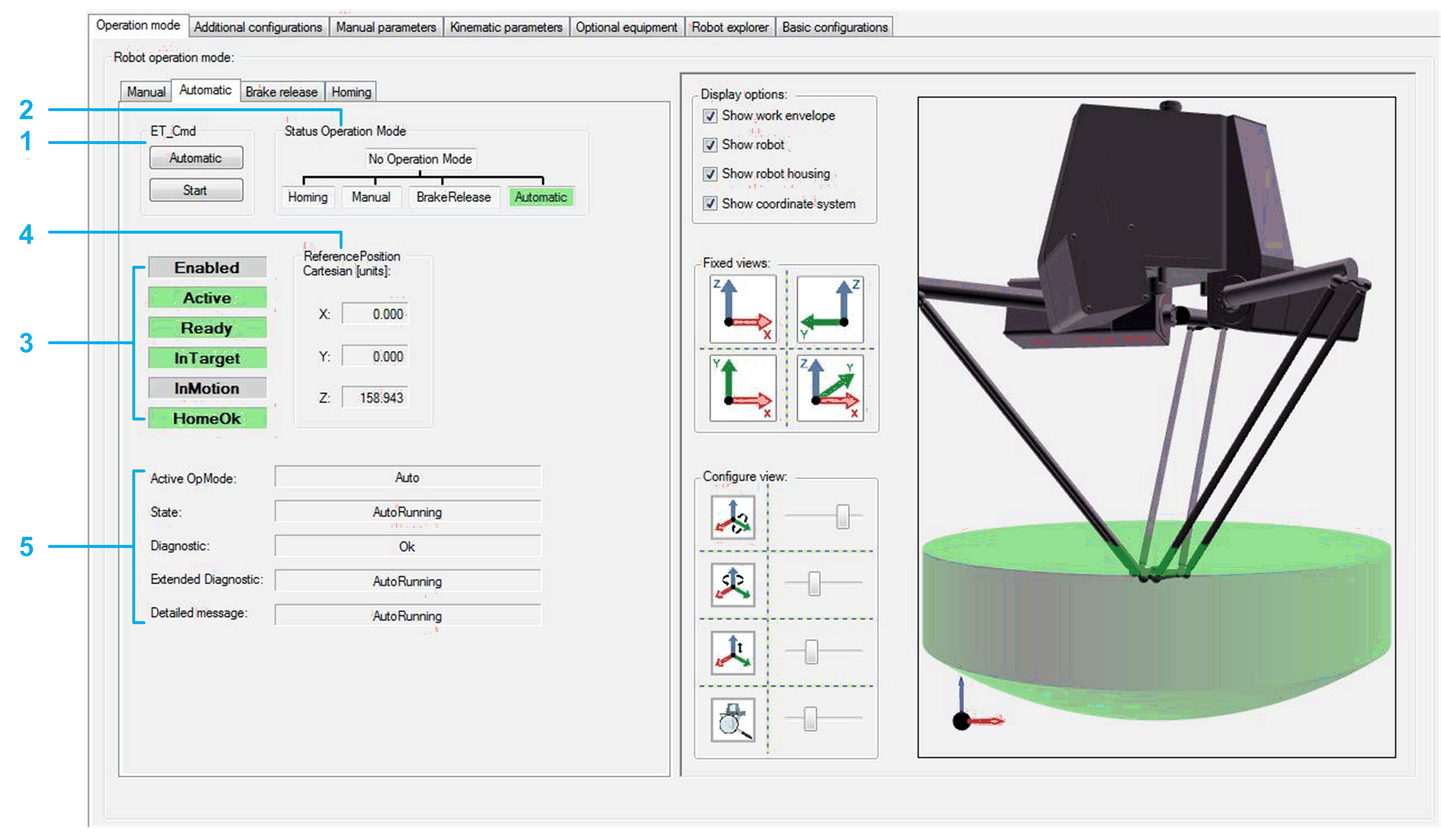
The left-hand side of the tab provides feedback and diagnostic information on the robot.
-
The right-hand side of the tab displays the robot movements in a 3D visualization. The visualization can be configured (refer to above).

|
1 |
If the module is not in the operation mode , click the button to send the command RM.ET_Cmd.Auto, and then click the button to send the command RM.ET_Cmd.Start. If the operation mode is accepted, the background color of the operation mode status switches to green. |
|
2 |
Displays the operation mode of the module. |
|
3 |
|
|
4 |
Detailed information can be found under: IF_RobotFeedback.rstRefPositionTCP in Robotic Library Guide. |
|
5 |
Diagnostics of the robot module. Detailed information can be found under: ET_DiagExt in RoboticModule Library Guide. |
Brake Release Tab
-
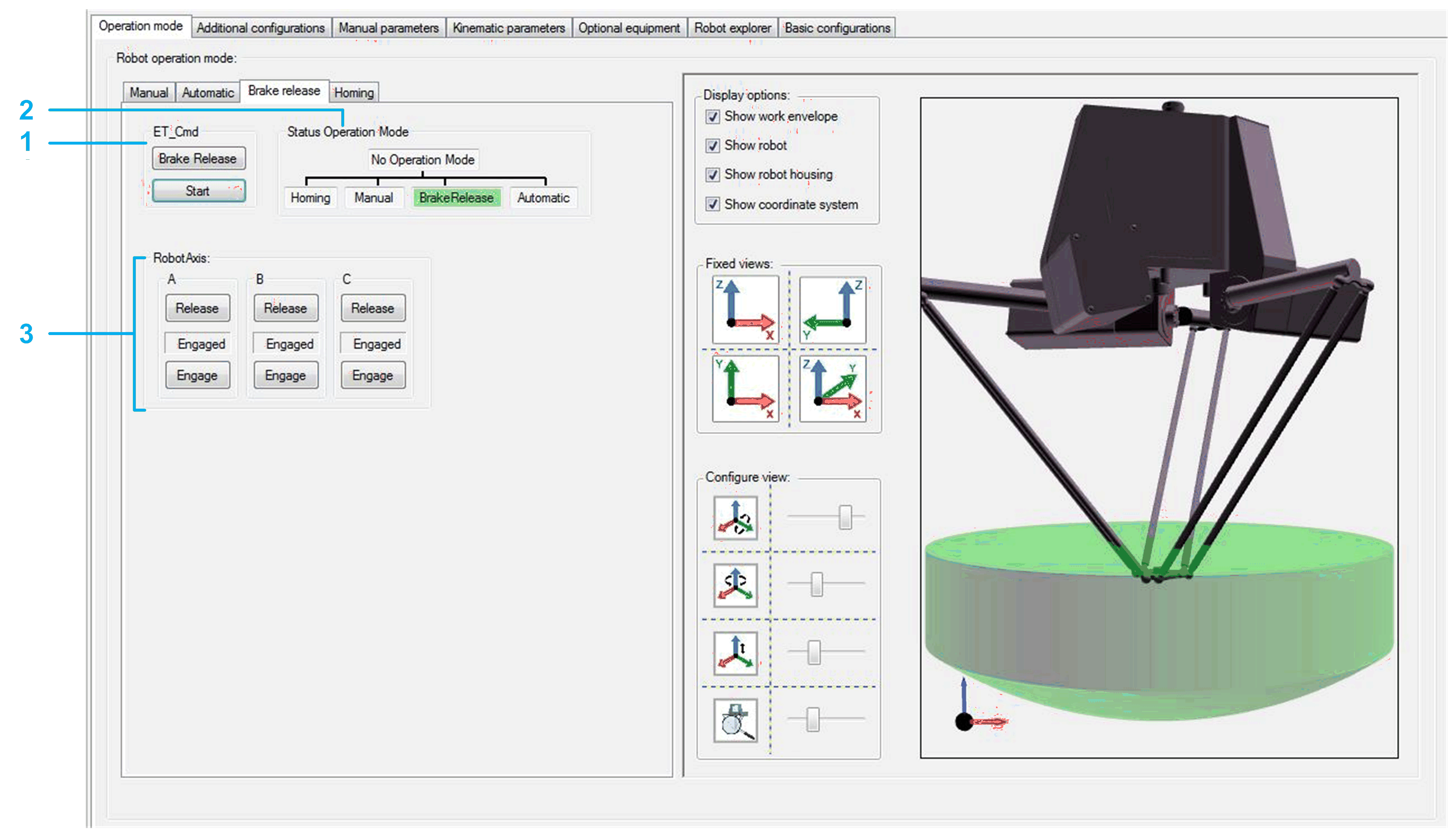
The left-hand side of the tab helps you to release/engage the brake(s) of one or several robot axes.
-
The right-hand side of the tab displays the robot movements in a 3D visualization. The visualization can be configured (refer to above).

|
1 |
If the module is not in the operation mode , click the button to send the command RM.ET_Cmd.BrakeRelease, and then click the button to send the command RM.ET_Cmd.Start. If the operation mode is accepted, the background color of the operation mode status switches to green. |
|
2 |
Displays the operation mode of the module. |
|
3 |
The indicator between the and the button displays the state of the respective brake. |
Homing Tab
-
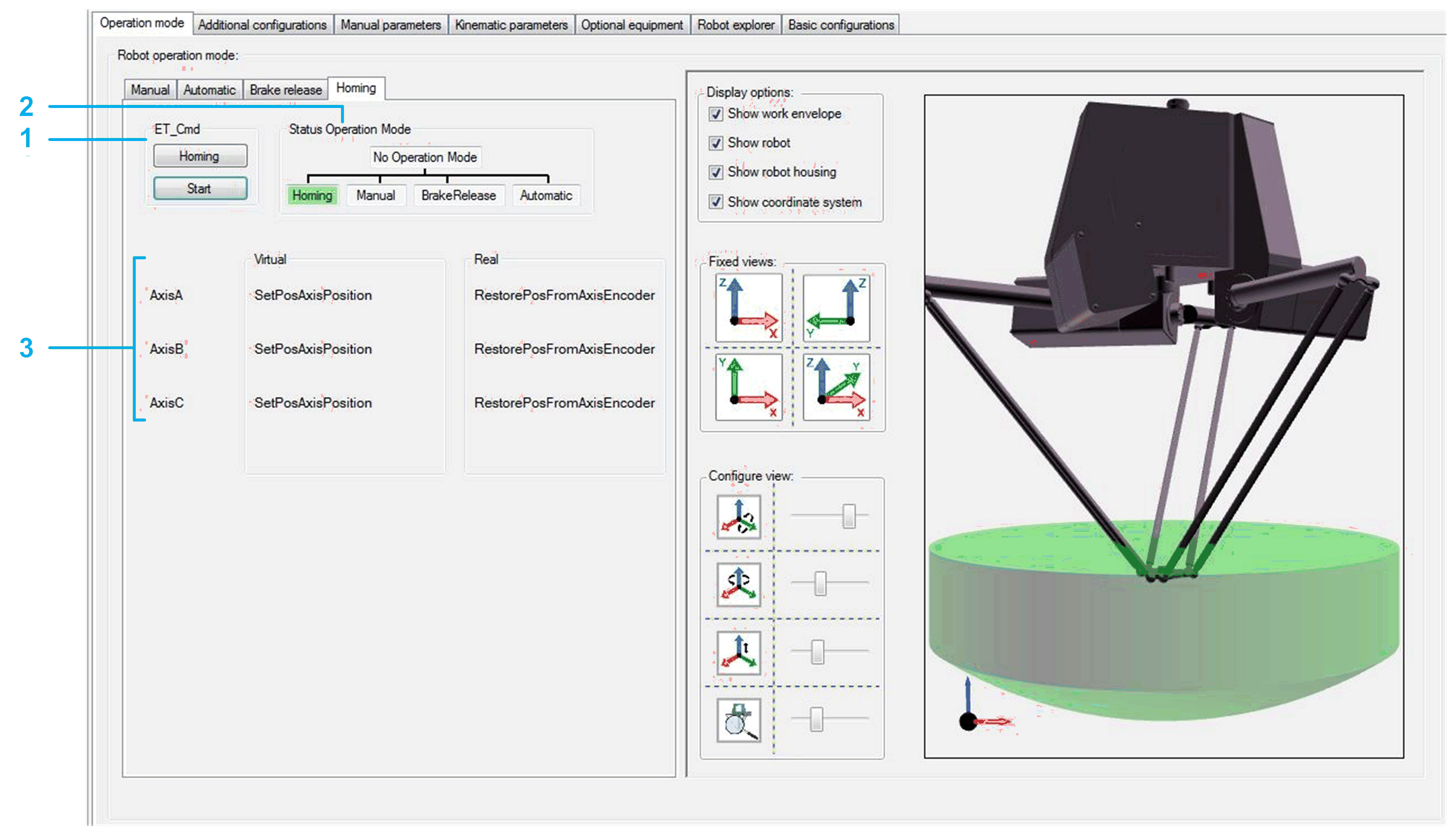
The left-hand side of the tab displays the homing mode of the robot axes.
-
The right-hand side of the tab displays the robot movements in a 3D visualization. The visualization can be configured (refer to above).

|
1 |
If the module is not in the operation mode , click the button to send the command RM.ET_Cmd.Homing, and then click the button to send the command RM.ET_Cmd.Start. If the operation mode is accepted, the background color of the operation mode status switches to green. |
|
2 |
Displays the operation mode of the module. |
|
3 |
Displays the configured homing mode of the respective axis in case of working mode and working mode . |
|
4 |
Displays the present homing modes for homing OnInit and OnHoming. |