This section provides a description of the electrical and input/output characteristics of the TM3RDM32R expansion modules.
See also Environmental Characteristics.
|
|
|
FIRE HAZARD |
|
oUse only the correct wire sizes for the current capacity of the I/O channels and power supplies. oFor relay output (2 A) wiring, use conductors of at least 0.5 mm2 (AWG 20) with a temperature rating of at least 80 °C (176 °F). oFor common conductors of relay output wiring (4 A), or relay output wiring greater than 2 A, use conductors of at least 1.0 mm2 (AWG 16) with a temperature rating of at least 80 °C (176 °F). |
|
Failure to follow these instructions will result in death or serious injury. |
|
|
|
UNINTENDED EQUIPMENT OPERATION |
|
Do not exceed any of the rated values specified in the environmental and electrical characteristics tables. |
|
Failure to follow these instructions can result in death, serious injury, or equipment damage. |
TM3RDM32R digital expansion module:
o16 channel 24 Vdc sink/source inputs
o2 common lines for inputs
o16 channel 2 A relay outputs
o4 common lines for outputs
oRemovable screw terminal block
The following figure shows the status LEDs:
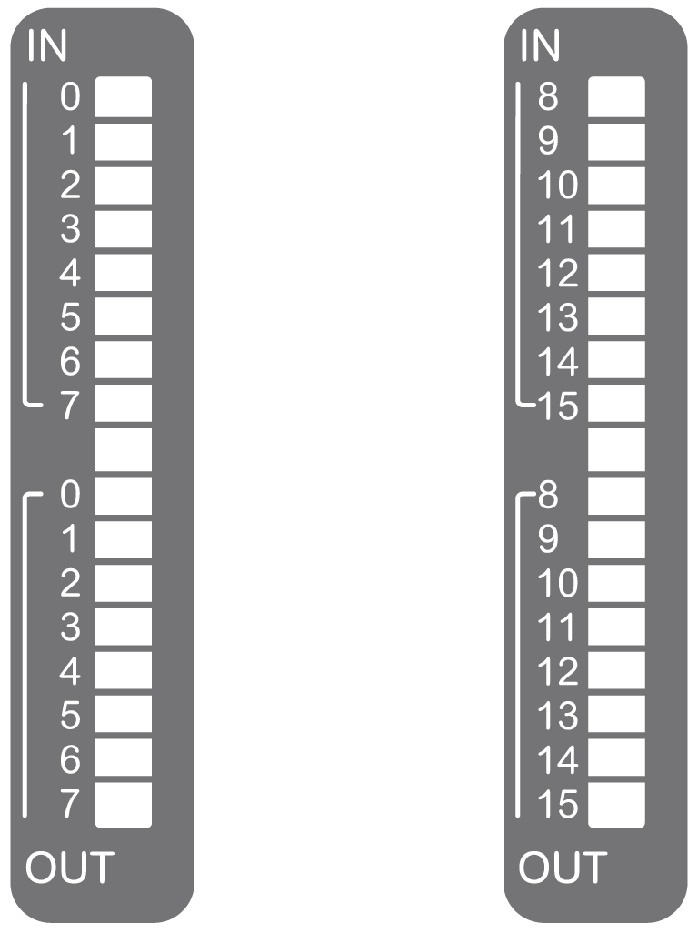
This table describes the status LEDs:
|
LED |
Color |
Status |
Type |
Description |
|---|---|---|---|---|
|
0...15 |
Green |
On |
Input |
The channel is activated |
|
Off |
The channel is deactivated |
|||
|
0...15 |
Green |
On |
Output |
The channel is activated |
|
Off |
The channel is deactivated |
The following diagrams show the external dimensions for the TM3RDM32R expansion modules:
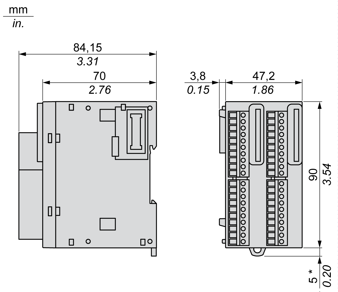
NOTE: * 8.5 mm (0.33 in) when the clamp is pulled out.
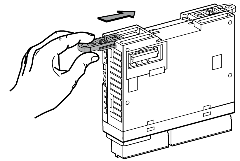
Insert the mounting strip into the slot at the top of the module:
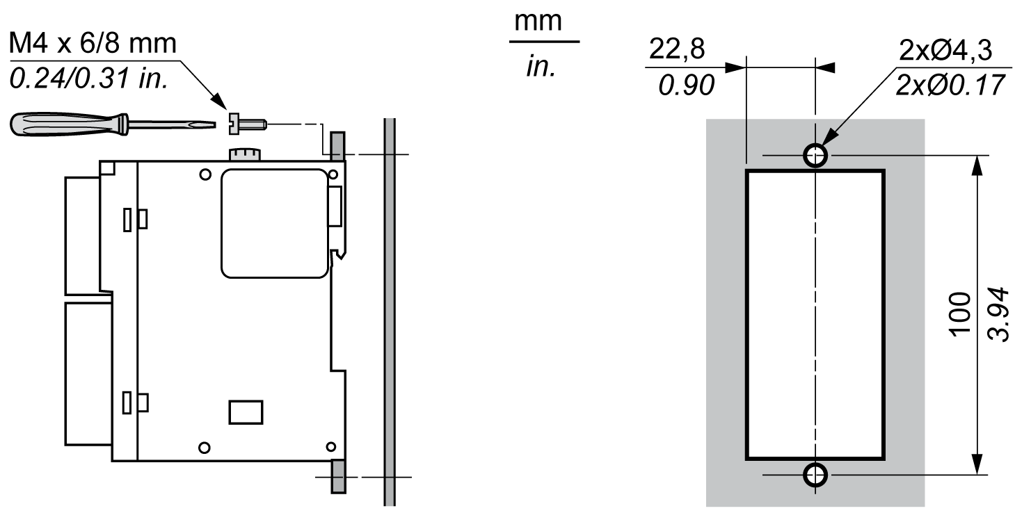
The following diagram shows the mounting holes layout for the TM3RDM32R expansion module:
|
Characteristic |
Value |
||
|---|---|---|---|
|
Input |
|||
|
Number of input channels |
16 inputs |
||
|
Input type |
Type 1 (IEC/EN 61131-2) |
||
|
Input Logic type |
Sink/Source |
||
|
Rated input voltage |
24 Vdc |
||
|
Output |
|||
|
Number of output channels |
16 outputs |
||
|
Contact type |
NO (Normally Open) |
||
|
Rated output voltage |
24 Vdc / 220 Vdc |
||
|
Rated output current |
2 A |
||
|
Connection and cable types |
|||
|
Connection type |
Removable screw terminal blocks |
||
|
Cable type and length |
Type |
Unshielded |
|
|
Length |
Input: max. 50 m (164 ft) Output: max. 150 m (490 ft) |
||
|
Weight |
208 g (7.34 oz) |
||
The table below describes the input characteristics of the TM3RDM32R:
|
Characteristic |
Value |
||
|---|---|---|---|
|
Number of input channels |
16 inputs |
||
|
Number of channels groups |
2 common lines for 16 channels |
||
|
Input type |
Type 1 (IEC/EN 61131-2) |
||
|
Logic type |
Sink/source |
||
|
Rated input voltage |
24 Vdc |
||
|
Input voltage range |
0...28.8 Vdc |
||
|
Rated input current |
5 mA |
||
|
Input impedance |
4.7 kΩ |
||
|
Input limit values |
Voltage at state 1 |
> 15 Vdc (15...28.8 Vdc) |
|
|
Voltage at state 0 |
< 5 Vdc (0..5 Vdc) |
||
|
Current at state 1 |
> 2.5 mA |
||
|
Current at state 0 |
< 1.5 mA |
||
|
Turn on time |
4 ms |
||
|
Turn off time |
4 ms |
||
|
De-rating |
0...55 °C (32...131 °F) |
See Input de-rating |
|
|
Isolation |
Between input and internal logic |
500 Vac / 800 Vdc |
|
|
Between input group and output group |
1500 Vac / 2500 Vdc |
||
|
Between input groups |
500 Vac / 800 Vdc |
||
|
Connection type |
Removable screw terminal block |
||
|
Connector insertion/removal durability |
Over 100 times |
||
|
Current draw on 5 Vdc internal bus |
95 mA |
||
|
Current draw on 24 Vdc internal bus |
80 mA |
||
When using TM3RDM32R:
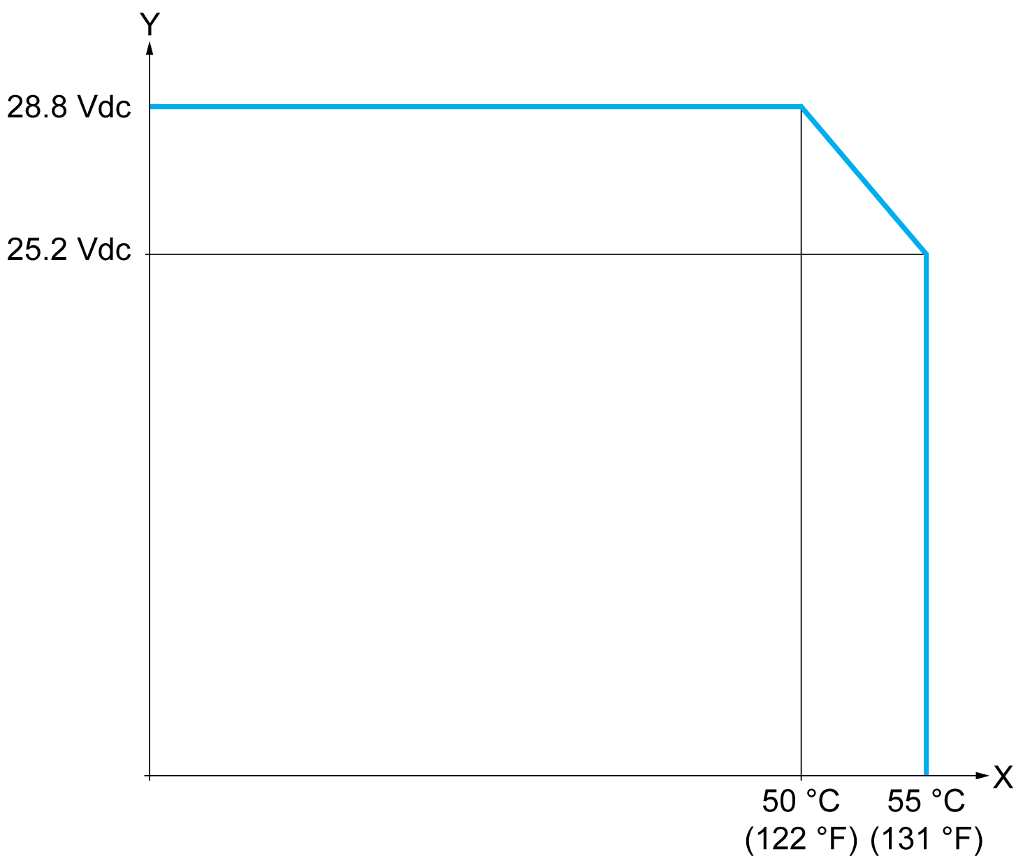
X Ambient temperature (°C / °F)
Y Input voltage
The table below describes the output characteristics of the TM3RDM32R
|
Characteristic |
Value |
|
|---|---|---|
|
Number of output channels |
16 |
|
|
Number of channel groups |
4 common line for 16 channels |
|
|
Output type |
Relay |
|
|
Contact type |
NO (Normally Open) |
|
|
Rated output current |
2 A per output |
|
|
Maximum output current |
2 A per output 4 A per common |
|
|
Maximum output frequency |
With max. load |
0.1 Hz |
|
Without load |
5 Hz |
|
|
Turn on time |
Max. 10 ms |
|
|
Turn off time |
Max. 10 ms |
|
|
De-rating |
0...55 °C (32...131 °F) |
See Output de-rating |
|
Mechanical life |
20 million operations |
|
|
Electrical life under resistive load 2 A |
100,000 switching cycles at 45 °C (113 °F) |
|
|
Protection against short circuit |
No |
|
|
Isolation |
Between output and internal logic |
1500 Vac / 2500 Vdc |
|
Between input group and output group |
1500 Vac / 2500 Vdc |
|
|
Between output groups |
1500 Vac / 2500 Vdc |
|
|
Connection type |
Removable screw terminal block |
|
|
Connector insertion/removal durability |
Over 100 times |
|
|
Current draw on 5 Vdc internal bus |
95 mA |
|
|
Current draw on 24 Vdc internal bus |
80 mA |
|
|
NOTE: Refer to Protecting Outputs from Inductive Load Damage for additional information on this topic. |
||
When using TM3RDM32R:
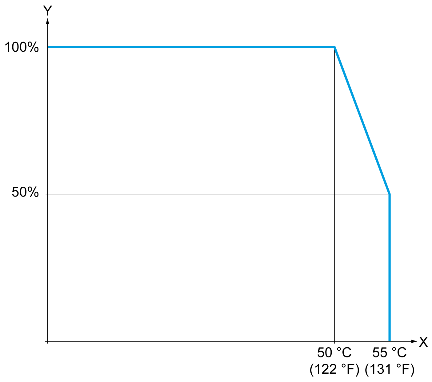
X Ambient temperature (°C / °F)
Y Output load current (%)
This table describes the power limitation of the TM3RDM32R expansion modules depending on the voltage, the type of load, and the number of operations required.
These expansion modules do not support capacitive loads.
|
|
|
RELAY OUTPUTS WELDED CLOSED |
|
oAlways protect relay outputs from inductive alternating current load damage using an appropriate external protective circuit or device. oDo not connect relay outputs to capacitive loads. |
|
Failure to follow these instructions can result in death, serious injury, or equipment damage. |
|
Power Limitations |
||||
|---|---|---|---|---|
|
Voltage |
24 Vdc |
120 Vac |
240 Vac |
Number of operations |
|
Power of resistive loads AC-12 |
– |
240 VA 80 VA |
480 VA 160 VA |
100,000 300,000 |
|
Power of inductive loads AC-15 (cos ϕ = 0.35) |
– |
60 VA 18 VA |
120 VA 36 VA |
100,000 300,000 |
|
Power of inductive loads AC-14 (cos ϕ = 0.7) |
– |
120 VA 36 VA |
240 VA 72 VA |
100,000 300,000 |
|
Power of resistive loads DC-12 |
48 W 16 W |
– |
– |
100,000 300,000 |
|
Power of inductive loads DC-13 L/R = 7 ms |
24 W 7.2 W |
– |
– |
100,000 300,000 |