Logic Processor Selection Switch and Confirmation Button
Overview
Whenever you make a change in the configuration (module or memory key replacement, or firmware update), you need to acknowledge the change on the Safety Logic Controller using the selection switch and the confirmation button.
Description of the Selection Switch Functions of TM5CSLC100FS and TM5CSLC200FS
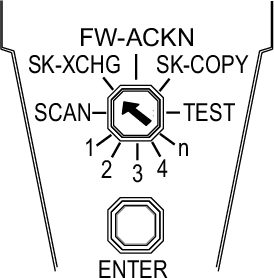
The following table describes the selectable functions of TM5CSLC100FS and TM5CSLC200FS:
|
Selection switch position |
Function |
Description |
|---|---|---|
|
FW-ACKN |
Module firmware update |
To acknowledge the firmware update on one or more modules (1) |
|
SK-XCHG |
To confirm the memory key replacement(1) |
|
|
Unlabeled position between SK-XCHG and FW-ACKN. |
To format the memory key. |
|
|
SK-COPY |
To copy the configuration data from the memory key to the safety logic(1) |
|
|
SCAN |
Scan |
To perform a module scan |
|
TEST |
To perform an LED indicator test |
|
|
1, 2, 3, 4, n |
Module(s) replacement |
To confirm the replacement of 1, 2, 3, 4 or more than 4 module(s) |
|
(1) Triggers an automatic restart. |
||
Description of the Selection Switch Functions of TM5CSLC300FS and TM5CSLC400FS
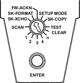
The following table describes the selectable functions of TM5CSLC300FS and TM5CSLC400FS:
|
Selection switch position |
Function |
Description |
|---|---|---|
|
FW-ACKN |
Module firmware update |
To acknowledge the firmware update on one or more modules |
|
SK-FORMAT |
Formatting the Memory Key |
To format the memory key(1) |
|
SETUP MODE |
To enable or disable(1) the setup mode. |
|
|
CLEAR |
Clear data |
This function is unsupported.(1) |
|
SK-XCHG |
To confirm the memory key replacement |
|
|
SK-COPY |
To copy the configuration data from the memory key to the safety logic(1) |
|
|
SCAN |
Scan |
To perform a module scan |
|
TEST |
To perform an LED indicator test |
|
|
1, 2, 3, 4, n |
Module(s) replacement |
To confirm the replacement of 1, 2, 3, 4 or more than 4 module(s) |
|
(1) Triggers an automatic restart. |
||
Confirming a Function (except the Function Formatting the Memory Key)
To confirm a configuration change, proceed as follows:
|
Step |
Action |
|---|---|
|
1 |
Select the desired function by means of the selection switch.
NOTE: If you do not place the selection switch properly, the LED ENTER flashes for 5 s to display a detected error.
Example: To replace one specific module, place the selection switch on 1. If the selection switch is not set to 1 when only one module was replaced, an error is detected and the LED ENTER flashes for 5 s. |
|
2 |
Press the confirmation button for 0.5 to 5 s to receive a confirmation. Result: After 0.5 s, the LED ENTER is illuminated. |
|
3 |
Release the confirmation button. Result: The LED ENTER remains illuminated for additional 0.8 s. |
|
NOTE: If you release the confirmation button before 0.5 s, it has no effect. If you press the confirmation button longer than 5 s, the LED ENTER flashes for 5 s to display a detected error.
|
|
Confirming the Function Formatting the Memory Key
For information on how to confirm the formatting of the memory key, refer to the description for Formatting the Memory Key.
Firmware Update
-
A firmware update is indicated by the FW-ACKN status and must be confirmed with the FW-ACKN selection switch.
-
After firmware modification, run a full functional test.
| DANGER | |
|---|---|
Selection Switch SETUP MODE of TM5CSLC300FS and TM5CSLC400FS
-
The setup mode supports you during commissioning.
-
An active setup mode is indicated by the LED FS-STATUS (refer to Description of the Logic Processor LED Indicators for TM5CSLC300FS and TM5CSLC300FS) and an entry in the Safe Logger.
-
The setup mode can be activated and deactivated using the SlcRemoteController library (refer to SlcRemoteController Library Guide) or using the selector switch and confirmation button on your controller.
-
When the setup mode is active, the acknowledgement requests , and are no longer required.
| DANGER | |
|---|---|
| DANGER | |
|---|---|