TM7SDI8DFS Digital Input Safety Module (SLCv2)
Module type/safety-related fields of application
Digital input safety-related module, 8 safety-related input channels, 2 standard (non-safety-related) input channels, 2 pulse outputs, 24 VDC, input filter configurable by software, 2 standard (non-safety-related) output channels, 24 VDC.
Output protection: thermal switch-off of individual channels if over-current or short-circuit occurs, integrated protection for switching inductive loads, 0.6 A total rated current.
Schneider Electric safety-related modules can be used in safety-related applications according to:
-
EN ISO 13849, PL e
-
IEC 62061, SIL 3
-
IEC 61508, SIL 3
Group: Basic
Parameter: MinRequiredFWRev
|
Default value |
Basic Release |
|
Unit |
-/- |
|
Description |
This parameter is only relevant in case of implementing other firmware versions than the manufacturer-loaded version. To enter the operational state, the firmware version parameterized here or a newer version must be installed on the module.
The firmware version selected here is particularly important with regard to parameters or process data items that have been implemented with a particular firmware version. If the device you are currently working with has new parameters or process data items, the following applies: if MinRequiredFWRev is set to an incorrect value, either the SLC will not enter the operational run status or the new parameters/process data items will not be taken into account by the SLC. Refer to the hazard message below this table.
Further Information:
Information on newly added parameters or process data items can be found in the Release Notes you received with the firmware package. The Release Notes also describe how to determine the firmware version that is currently installed on the safety-related device. |
| WARNING | |
|---|---|
Parameter: Optional
|
Default value |
No |
|
Unit |
-/- |
|
Description |
The module can be configured as optional using this parameter. Optional modules do not have to be available (physically present or communicative), i.e., if an optional module is unavailable, this is not signaled by the Safety LogicController. This parameter does not influence the module signal or status data. |
|
Possible values |
|
The Optional parameter is a mechanism to scale your safety-related system for various configurations of your machine design. However, it may be the case that the module(s) that you have designated as optional may be required in some of your alternative machine configurations.
| WARNING | |
|---|---|
Group: SafetyResponseTime
The safety response time is the time between the arrival of the sensor signal on the input channel of a safety-related input module and the shut-off signal at the output channel of a safety-related module. For further and detailed background information, refer to the topic "Safety Response Time for SLCv2 " in the "Machine Expert – Safety - User Guide".
The parameters in this group influence the safety response time of the Safety Logic Controller system. The parameters SafeDataDuration and ToleratedPacketLoss in this group are only applied to the module if ManualConfiguration is set to 'Yes'.
Parameter: ManualConfiguration
|
Default value |
No |
|
Unit |
-/- |
|
Description |
Specifies whether the module uses its safety response time-relevant parameters (SafeDataDuration and ToleratedPacketLoss) or the values specified in the 'SafetyResponseTimeDefaults' parameter group of the Safety Logic Controller. Managing parameters per module optimizes the system to application-specific requirements regarding the safety response time. |
|
Parameter value |
|
Parameter: SafeDataDuration
|
Default value |
200 |
|
Value range Step size |
25...9,380 1 |
|
Unit |
100 µs |
|
Description |
This parameter influences the safety response time of the safety-related application. Specifies the maximum permissible time for data transmission from a safety-related producer to a consumer, that is, from an input module to the SLC, or from the SLC to an output module. Based on this parameter value and the value of the 'ToleratedPacketLoss' parameter (described below), and further module-specific processing times, the Safety Response Time (SRT) is calculated. Verify the SRT resulting from the parameter values entered here using the 'Response Time Calculator' dialog in Machine Expert – Safety (menu item 'Project > Response Time Calculator'). |
|
Value calculation |
The risk analysis you have performed for your safety-related application delivers the maximum allowed overall response time of the safety function and, as part of this, the safety function response time (SRT) of the signal chain. The SRT is composed of the following partial time values:
with
(including configured filter/delay times),
(including configured delay times),
This maximum SRT value is the basis for the calculation of the SafeDataDuration (SDD) and the ToleratedPacketLoss (TPL) value you must enter as the parameter value in the grid. From the allowed SRT, deduct the processing times of the safety-related input module (SPTi) and the output module (SPTo). The result is the total maximum permissible time for the safety-related data transmission on the complete safety-related path, i.e., from the input module to the output module. As the SafeDataDuration parameter relates to only one transmission path (input module -> SLC or SLC -> output module), you must divide the value by 2 to get the required value to be entered in the parameter grid. If a packet loss greater than 0 is tolerated, this must also be considered. The calculation equation is as follows:
With
|
Parameter: ToleratedPacketLoss
|
Default value |
1 |
|
Value range Step size |
0...10 1 |
|
Unit |
Data packets |
|
Description |
Specifies the maximum allowed number of lost packets during data transmission. The number of tolerated packet losses affects the safety response time. Based on this parameter value and the value of the 'SafeDataDuration' parameter, the Safety Response Time (SRT) of the system is calculated. Verify the SRT resulting from the parameter values entered here using the 'Response Time Calculator' dialog in Machine Expert – Safety (menu item 'Project > Response Time Calculator'). |
Group: Connector01 up to Connector04
Parameter: SafeDigitalInputxxPulseMode
|
Default value |
Internal |
|
Unit |
-/- |
|
Description |
Specifies the pulse mode of the input channel. |
|
Possible values |
NOTE:
Also observe the safety-related notes and hazard messages in the device manual. |
|
1 |
With the configuration 'PulseMode = no Pulse', the module itself is not able to detect wiring errors. Internal errors, however, are still detected. All errors resulting from incorrect, damaged or disconnected wiring must be handled through supplementary measures in accordance with EN ISO 13849-2:2012 or by the connected device. |
| WARNING | |
|---|---|
Parameter: SafeDigitalInputxxFilterOff
|
Default value |
0 |
|
Value range Step size |
0...500,000 1 |
|
Unit |
µs |
|
Description |
Configures a switch-off filter for the channel to remove potentially disruptive "low phases" on the input signal. Configuring a switch-off filter increases the data processing time of the safety-related module and therefore also the safety response time. Refer to the first hazard message below this table. Configuring a switch-off filter causes input signals with a "low phase" shorter than the switch-off filter to be filtered out. If this results in unintended operation of your equipment, the FilterOff parameter must be set to 0. Extending the "low phase" with a switch-on filter (FilterOn parameter) is not possible in these cases. Refer to the second hazard message below this table. |
| WARNING | |
|---|---|
| WARNING | |
|---|---|
Parameter: SafeDigitalInputxxFilterOn
|
Default value |
200,000 |
|
Value range Step size |
0...500,000 1 |
|
Unit |
µs |
|
Description |
Sets the switch-on filter for the channel. Input signals can be debounced with the switch-on filter. Furthermore, using this function, you can extend a module switch-off signal that would otherwise be too short. Input signals with a "low phase" shorter than the safety response time can be lost. Such signals should be extended accordingly using the FilterOn parameter ('switch-on filter') on the input module. |
Parameter: DiscrepancyTimexx
|
Default value |
0 |
|
Value range Step size |
0...500,000 1 |
|
Unit |
µs |
|
Description |
This parameter is only available for odd-numbered channels. If set, it combines the current channel with the next channel for two-channel evaluation. (Setting channel n combines n and n+1.) The value specifies the maximum time interval for the two-channel evaluation, during which the status of both physical individual channels may be undefined without triggering an error. Whether the channels are monitored for antivalence or equivalence depends on the used process data items: the module provides SafeEquivalentInputs as well as SafeAntivalentInputs. Violation of the DiscrepancyTime can be monitored by evaluating the SafeEquivalentOK or SafeAntivalentOK process data items for the module in the safety-related application. |
Parameter: TwoChannelProcessingModexx
|
Default value |
none |
|
Unit |
-/- |
|
Description |
This parameter is only available for the first channel of each channel pair, i.e., for odd-numbered channels. Specifies the evaluation type of the channel. |
|
Possible values |
NOTE:
After having parameterized 'Antivalent' or 'Equivalent', the process data item resulting from the two-channel evaluation SafeTwoChannelInputxxyy has to be used in the code. The setting 'none' requires the use of the appropriate single-channel process data item SafeDigitalInputxx. |
Parameter: InvertDigitalInputxx
|
Default value |
No |
|
Unit |
- |
|
Description |
This parameter is only available for input channels located on the device connector 1 (safety-related input channels 01 and 02, and standard input channel 01) and connector 2 (safety-related input channels 03 and 04, and standard input channel 02). Activates or deactivates inverted evaluation of the channel. |
|
Possible values |
|
Parameter: InvertDigitalOutputxx
|
Default value |
No |
|
Unit |
- |
|
Description |
This parameter is only available for output channels located on the device connector 1 (standard output channel 01) and connector 2 (standard output channel 02). Activates or deactivates inverted signal output of the respective standard output channel. |
|
Possible values |
|
Process data items of the module
Purpose and use of process data items
Each module provides process data items (signals). Process data items can be:
-
I/O signals delivered from or written to a module terminal.
-
diagnostic signals for evaluating the status of input/output channels or the entire module.
-
control signals, for example, for enabling a channel or adjusting the module.
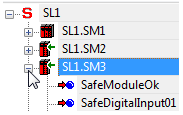
The available process data items of a module are listed under the module node in the tree on the left of the 'Devices' window. To display and use the process data items, expand the module node in the tree by clicking the '+' symbol.
Example
The module with the ID SL1.SM3 provides (among others) the diagnostic signal SafeModuleOK and the input signal SafeDigitalInput01.
From the devices tree, process data items can be inserted into the safety-related FBD/LD code by drag & drop (see following procedure). On insertion into the code, a standard (non-safety-related) or safety-related global variable is created (depending on the data type of the process data item).
Procedure: How to insert process data items into the code
-
Open the code worksheet where you want to insert the process data item and create/use the global variable assigned to it.
-
In the 'Devices' window, open the devices tree on the left and expand the module (tree node) which contains the process data item to be used.
-
Drag the process data item into the code worksheet. When releasing the mouse button, the 'Variable' dialog appears.
To insert a Boolean variable as a contact into the graphical code, hold the <CTRL> key down when releasing the mouse button after dragging the variable from the device terminal grid into the code worksheet.
-
In the 'Variable' dialog, a default name is proposed which is derived from the process data item name. Accept the proposed name, select an existing global variable, or declare a new global variable by entering a new 'Name', defining the 'Data Type' and selecting a 'Group'.
-
Confirm the 'Variable' dialog by clicking 'OK'.
The rectangle shape of the variable is now added to the cursor. It can be dropped at the desired position with a click. You can directly connect the variable to another object (e.g., a formal parameter as shown in the following example) or dropped at any free position.
Data direction depends on the signal type
Input signals can only be read and output signals can be written by the safety-related application.
Diagnostic signals can be used to evaluate and monitor the status of the safety-related module or individual I/O channels, for example. Therefore, global variables created for and assigned to diagnostic signals can be read by the application.
Control signals can be used to enable the module operation or to adjust/adapt the module for the present use case (for example, by setting a measurement range or a particular module behavior). The global variables created for and assigned to control signals can be written by the application, thus controlling the module.
Representation of the process data items in the devices tree:
|
Icon |
Signal type |
Access type |
|---|---|---|

|
Safety-related input signal or diagnostic signal. |
read |

|
Non-safety-related input signal (only available for the Safety Logic Controller). |
read |

|
Non-safety-related output signal (only available for the Safety Logic Controller) or control signal. |
write |

|
Safety-related output or control signal. |
write |
If a standard (non-safety-related) signal is connected to a physical input or output, the data type of the corresponding global variable must be modified from safety-related to standard (e.g., from SAFEBOOL to BOOL) to rule out an incorrect use of the signal in the code. The same applies if a safety-related signal is used only as standard signal in the code. Modifying the data type can either be done in the appropriate variables worksheet or using type converter functions.
| WARNING | |
|---|---|
In the following, the I/O, diagnostic and control signals of the present module are listed and described in the order they are listed in the devices tree.
SafeModuleOK
|
Description |
Indicates the status of the communication between the safety-related module and the Safety Logic Controller and therefore, from safety-related application perspective, the module status itself. |
|
Signal type |
Diagnostic |
|
Data type |
SAFEBOOL |
|
Access type |
Variable can be read by the safety-related application |
|
Possible values |
SAFEFALSE:
SAFETRUE:
|
Mandatory assignment validation for the SafeModuleOK data item:
The verification/validation of the assignment of each process data item to a global I/O variable is mandatory. This particularly applies to the SafeModuleOK process data item which is available for each safety-related module and indicates its status. As the SafeModuleOK data item cannot be written to, e.g., by applying a signal to a module input, the module to be verified must be physically removed from the TM5 bus. As a result, SafeModuleOK switches to SAFEFALSE and the assigned global I/O variable must follow. For further information on the steps to remove and reinsert a module, refer to the user manual of the module.
| WARNING | |
|---|---|
SafeDigitalInputxx
|
Description |
Digital input signal from the single-channel command device or sensor connected to the module. xx specifies the channel number of the module.
NOTE:
For equivalence or antivalence monitoring at an input channel pair, use the respective combined signal xxyy instead of this single channel. The validity of this input signal is confirmed by the related diagnostic signal SafeChannelOKxx and/or SafeInputOKxx (depending on the module). Depending on the results of the risk analysis you carried out for your application, the diagnostic signal must be evaluated each time the SafeDigitalInputxx signal is used in the safety-related application. The value SAFEFALSE of the diagnostic signal indicates an invalid SafeDigitalInputxx value. In this case, the SafeDigitalInputxx signal must not be further used, processed, or evaluated in the safety-related application. Refer to the hazard message below this table. |
|
Signal type |
I/O signal |
|
Data type |
SAFEBOOL |
|
Access type |
Variable can be read by the safety-related application |
|
Possible values |
If SafeModuleOK = SAFETRUE and the channel-related diagnostic signal(s) SafeChannelOKxx and/or SafeInputOKxx = SAFETRUE (depending on the module), the following applies: SAFETRUE: Digital input channel is set to true. SAFEFALSE: Digital input channel is set to false. |
|
Relevant module parameters |
In the parameter group with the same channel number xx:
The related parameter descriptions can be found above in this topic. |
| WARNING | |
|---|---|
SafeTwoChannelInputxxyy
|
Description |
Signal resulting from equivalence or antivalence monitoring of the input signals at the channel pair xxyy. Whether equivalence or antivalence evaluation is performed, depends on the module parameter TwoChannelProcessingMode (see description above). Depending on the set processing mode, the following applies:
Equivalence/antivalence between the involved channels must be established before the interval specified with the DiscrepancyTime parameter has elapsed. Otherwise, the related diagnostic signal SafeTwoChannelOKxxyy switches to SAFEFALSE and the channel is disabled. The validity of this input signal is confirmed by the related diagnostic signal SafeTwoChannelOKxxyy. Depending on the results of the risk analysis you carried out for your application, the diagnostic signal must be evaluated each time the SafeTwoChannelInputxxyy signal is used in the safety-related application. The value SAFEFALSE of the diagnostic signal indicates an invalid SafeTwoChannelInputxxyy value. In this case, the SafeTwoChannelInputxxyy signal must not be further used, processed, or evaluated in the safety-related application. Refer to the hazard message below this table. |
|
Signal type |
I/O signal |
|
Data type |
SAFEBOOL |
|
Access type |
Variable can be read by the safety-related application |
|
Possible values |
If TwoChannelProcessingMode = Equivalent and SafeModuleOK = SAFETRUE and SafeTwoChannelInputxxyy = SAFETRUE:
If TwoChannelProcessingMode = Antivalent and SafeModuleOK = SAFETRUE and SafeTwoChannelInputxxyy = SAFETRUE:
|
|
Relevant module parameters |
In the parameter group of the respective connector:
The related parameter descriptions can be found above in this topic. |
| WARNING | |
|---|---|
SafeTwoChannelOKxxyy
|
Description |
Diagnostic signal which indicates the status of the equivalence or antivalence signal evaluation at the safety-related digital input channel pair xx and yy. Whether equivalence or antivalence evaluation is performed, depends on the module parameter TwoChannelProcessingMode (see description above). This diagnostic signal confirms the validity of the SafeTwoChannelxxyy signal. Depending on the results of the risk analysis you carried out for your application, the diagnostic signal must be evaluated each time the SafeTwoChannelxxyy signal is used in the safety-related application. The value SAFEFALSE of the diagnostic signal indicates an invalid SafeTwoChannelxxyy value. In this case, the SafeTwoChannelxxyy signal must not be further used, processed, or evaluated in the safety-related application. Refer to the hazard message below this table.
NOTE:
To detect error status conditions of modules/channels within your application, diagnostic signals must be evaluated in the safety-related code. A programming example and further information can be found in the topic "Monitoring/evaluating diagnostic information of the machine". |
|
Signal type |
Diagnostic signal |
|
Data type |
SAFEBOOL |
|
Access type |
Variable can be read by the safety-related application |
|
Possible values |
SAFEFALSE:
SAFETRUE:
NOTE:
Also observe the respective LED indicator(s) of the affected modules for the error indication. |
| WARNING | |
|---|---|
SafeInputOKxx
|
Description |
Diagnostic signal which indicates the status of the safety-related digital input channel. xx specifies the channel number. This diagnostic signal confirms the validity of the SafeDigitalInputxx signal. Depending on the results of the risk analysis you carried out for your application, the diagnostic signal must be evaluated each time the SafeDigitalInputxx signal is used in the safety-related application. The value SAFEFALSE of the diagnostic signal indicates an invalid SafeDigitalInputxx value. In this case, the SafeDigitalInputxx signal must not be further used, processed, or evaluated in the safety-related application. Refer to the hazard message below this table.
NOTE:
To detect error status conditions of modules/channels within your application, diagnostic signals must be evaluated in the safety-related code. A programming example and further information can be found in the topic "Monitoring/evaluating diagnostic information of the machine". |
|
Signal type |
Diagnostic signal |
|
Data type |
SAFEBOOL |
|
Access type |
Variable can be read by the safety-related application |
|
Possible values |
SAFEFALSE:
SAFETRUE:
NOTE:
Also observe the respective LED indicator(s) of the affected modules for the error indication. |
| WARNING | |
|---|---|