Commissioning of Hold and Close Drives
The following points apply to both drives unless stated otherwise.
|
Step |
Action |
|---|---|
|
1 |
Set hold and close drives to factory settings. |
|
2 |
Configure correct motor control parameters. |
|
3 |
Configure brake logic control. |
|
4 |
Perform motor tuning and encoder test. |
|
5 |
Set the motor control mode to FVC. |
|
6 |
In drive menu application functions, disable preset speeds. Set command and reference channel to the fieldbus used. |
|
7 |
Configure the communication parameters, A power cycle of the drive is required after a modification of the communication configuration. |
|
8 |
In settings menu set the “K speed loop filter” to 100. This parameter influences how accurately the actual speed follows the target speed. The higher the value the more accurately Altivar drive responds to changing target speed. If motor speeds or torque tend to oscillate, it is possible to lower the value at a cost of lowering precision of virtual limit switch function during opening and closing. |
|
9 |
Enable torque limitation on the hold drive and set it to 0.1% resolution. The hold drive is torque limited during closing on stack. |
|
10 |
Disable detection of load slipping in encoder fault configuration in fault management. If load slipping fault detection is enabled during closing on stack, hold drive reports a load slipping fault. |
Commissioning of GrabControl Function Block
|
Step |
Action |
|---|---|
|
1 |
Without moving the motors verify that all commands and target speeds are being received correctly from the operator interface. |
|
2 |
Add two Altivar drives to the fieldbus configuration. Configure the communication parameters: oFrom controller to drives Both drives: Command word, Target speed, Acceleration, Deceleration Hold drive only: Motor torque limitation, Generator torque limitation oFrom drives to controller Both drives: Status word, Actual speed (Control effort), Encoder position value (PUC), Torque scope value, Motor current |
|
3 |
Instantiate the GrabControl FB in your program and parameterize it with initial parameters. |
|
4 |
If the torque scope values of both motors are connected to the FB directly, set the i_stPGC.xTrqScopeScale parameter to TRUE. Otherwise the torque values need to be scaled in the application by dividing it by 4.096 and the i_stPGC.xTrqScopeScale parameter must be set to FALSE. |
|
5 |
Instantiate it in a program executed in a cyclic task, preferably in the Master task. The same task should be a parent task for the fieldbus communications. Master task is the parent task by default. |
|
6 |
Configure the execution period of the corresponding task to a value in the range between 20 and 50 ms. |
|
7 |
Download the application, put it to run and verify status of the fieldbus. |
|
8 |
Calibrate open and closed positions of the grab. Following two steps describing calibration of closed and open positions may be performed in an arbitrary order. Incorrect calibration may be reset by rising edge on i_xGrabCalbRst input. |
|
9 |
Close the grab fully and calibrate the closed position by rising edge on i_xGrabCalbClosed. NOTE: When the grab is in good mechanical condition (no space between jaws when it softly closes), calibrate it in a state when the jaws are closed, but both hold and close cables are still fully tensioned. When the mechanics of the grab is not aligned perfectly, you may want to calibrate it in a little overclosed position (more load on close cables). |
|
10 |
Open the grab fully and calibrate the open position by rising edge on i_xGrabCalbOpen. |
|
11 |
Close the grab at slow speed and verify that it stops automatically when it reaches closed state. If it functions correctly, repeat this step at nominal speed. The grab should close softly without an impact of the jaws and jerk of the crane. If the grab was calibrated in a slightly over-closed position as described earlier, certain impact when the grab closes is acceptable and even desirable. |
|
12 |
Repeat the test for open position. The grab must open softly. Both, hold and close cables should be straight without slack in open position. |
|
13 |
Set the proportional gain for position synchronization i_stPGC.rKpPosSync. The default gain is 0.01 and the FB internally compensates for resolution of the encoder. Therefore it is not necessary to change the value when encoder with different resolution is used. |
|
14 |
Test the behavior of position synchronization. Set the i_xTrqShareEn input to FALSE or move the grab to a non-closed position to activate position synchronization q_wStat.5 = TRUE. Move the grab up and down by giving command to the hold drive without giving command to the close drive. Take a trace of actual torque, speeds of both motors and the position deviation output q_diEncPosDev. When the position deviation is higher than required and if the motor speeds and torques do not oscillate, increase the value of i_stPGC.rKpPosSync. If motor speeds and torques are oscillating, decrease the value of i_stPGC.rKpPosSync. |
|
15 |
Set the proportional gain for load sharing i_stPGC.rKpTrqShr. The default gain is 0.1. |
|
16 |
Test the behavior in load sharing. Close the grab and set the i_xTrqShareEn input to TRUE to activate load sharing q_wStat.6 = TRUE. Set the i_stPGC.wTrqAddOnClose parameter to 0. Move the grab up and down by giving command to the hold drive without giving command to the close drive. Take a trace of actual torque of both motors. Both torques should converge to the same value. When the torques do not converge fast enough, increase the value of i_stPGC.rKpTrqShr. If the torques are oscillating around a common average value, decrease the value of i_stPGC.rKpTrqShr. |
|
17 |
Set a value of i_stPGC.wTrqAddOnClose to a value of ~50 (5%) if it is required to keep higher torque on the close motor in order to keep the grab closed. The value may be modified later during tests with filled grab. Take a trace to test that the torque of close motor is higher than the torque of the hold motor by defined value and that the motor torques are stable. |
|
18 |
Configure a trace object in EcoStruxure Machine Expert containing actual speed, speed reference and actual torque of both motors and commands from the joystick. Add also bits from status word. (1,2,5,6,7) The trace is very useful during commissioning and for troubleshooting. |
|
19 |
Configure the closing on stack function. Set the value of i_stPGC.wClsHoldTrqLim to ~100 (10%). The FB will limit torque of the hold drive to this value during closing on stack. The value must be high enough to keep the hold cables straight and support the grab in upright position, but must be low enough to allow sinking of the grab to the material during closing. Set the i_stPGC.wClsHoldSpdRef to ~10% of the nominal speed of the motor. The speed may be increased if slack of the hold cables is not compensated for fast enough and decreased if straightening of hold cables lifts the closing grab. Configure the wClsClosedPosOfst parameter to 0, it may be increased later to help keeping the filled grab closed during vertical movement. Test the automatic closing on stack by laying an open grab on the stack and giving and keeping the command to activate closing on stack. Speed of the close motor can be modified during closing on stack. Speed of the hold motor is given by i_stPGC.wClsHoldSpdRef and i_stPGC.wClsHoldTrqLim. The grab must close fully and when the command is still being held it must softly lift the closed grab up. |
|
20 |
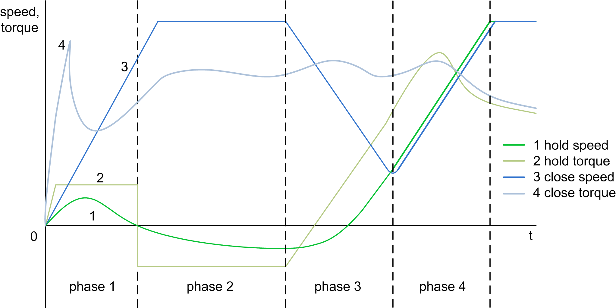
Following figure depicts speeds and torques of both drives and describes phases of the procedure: 
oPhase 1 Close axis accelerates in forward direction, closing the grab Hold axis has also a positive speed reference, but is torque limited, which prevents it from lifting the whole grab. Therefore it only straightens the slack cables and then stops. oPhase 2 Close axis continues to close the grab. Hold axis is pulled down by the weight of the grab because of its torque limitation. This allows for a proper filling of the grab. The amount of sinking of the grab is influenced by the parameter i_stPGC.wClsHoldTrqLim. oPhase 3 The grab is approaching the closed position. Close axis decelerates and the torque limitation of hold axis is gradually lifted. The hold axis accelerates and reaches the same speed as the close axis in the moment when the grab is fully closed oPhase 4 Both axes move in load sharing or position synchronization depending on setting of the parameter i_xTrqShareEn. The torques are equalizing and lifting of the filled grab continues |
|
21 |
If the grab is spilling when it’s lifted from the stack, increase the value of i_stPGC.wClsClosedPosOfst by 2 and repeat the closing on stack. Increase the value some more if necessary. The parameter causes a slight over-closing of the grab and helps to contain the material in a grab with less than optimal mechanical precision. When controlling a spider grab, leave this value at 0. When you are controlling a spider grab or any grabbing application where a grab might not close fully because of objects between the jaws, configure the i_stPGC.wClsTrqCloseThsh and i_stPGC.wClsTrqCloseTimeFltr parameters. Trace the torque value of close motor during opening and select an appropriate torque level for considering the grab closed. Configure a filter time to filter out torque peaks. |
|
22 |
Move the closed and filled grab upwards and downwards and trace actual torques of both motors. The torques should stabilize and the close torque should be higher than the hold torque by the value specified in i_stPGC.wTrqAddOnClose. If the torques do not converge fast enough, increase the value of i_stPGC.rKpTrqShr, if they oscillate, decrease it. If the grab spills its content, increase the value of i_stPGC.wTrqAddOnClose. |
|
23 |
Configure quick deceleration ramp. It helps reducing rope slack by allowing fast stop ramp in downwards direction when the grab is laid on the stack. Measure the torque of hold drive during downwards movement with open grab and the difference it makes when grab lands on the ground/stack and the movement continues with slack cables. Set the i_stPGC.wLowTrqDecRampThsh parameter lower than absolute value of torque with grab hanging on the cables and moving down. Test that the short ramp is used only when the grab lies on the stack. This function is not active while the grab is opening or closing during movement. |
|
24 |
If required, configure the optional scraping function. It allows scraping of rests of transported material from a hard flat surface. The function is similar to closing on stack, but it keeps contact with the surface until the grab is fully closed. The parameter i_stPGC.wScrapHoldTrqLim defines torque limitation of the hold drive during scraping. It defines how much force is applied on the surface. Set the value higher to apply less force on the surface during scraping. The value must be low enough to keep contact between jaws of the grab and the surface for the whole duration of scraping. |
|
25 |
If required, enable and test the optional rapid opening function. |
|
26 |
If the brakes on hold and close axes need a long time to open, it may lead to slack cables. This usually happens when a downward movement command is given right after the grab fully opened. The brake of the close motor is still open because it just finished the opening movement, but the brake of the hold drive is closed. Therefore the close drive starts to move immediately, but the hold drive waits until its brake opens. This delay causes more or less significant slack of close cables. The function block uses the parameter i_stPGC.wBrakTimeDelay to compensate for the brake delay. Set the value to the brake opening time in milliseconds. |
|
27 |
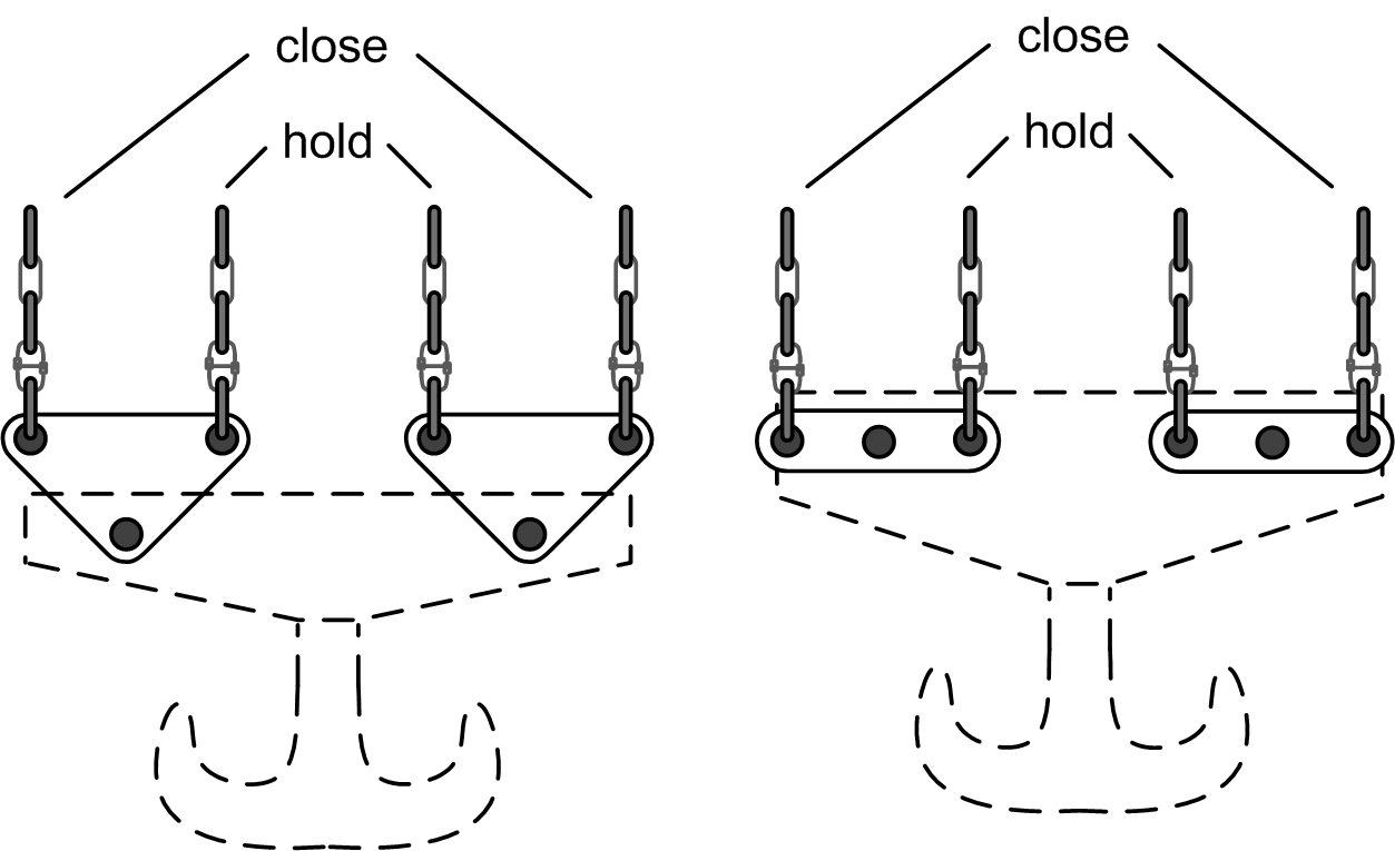
If required, test the hook mode. Hook mode allows usage of a hook on a four cable system. There are several hook types. Two of them are described here. The following figure is a hook type with two variants of hooks for four cable grabs: 
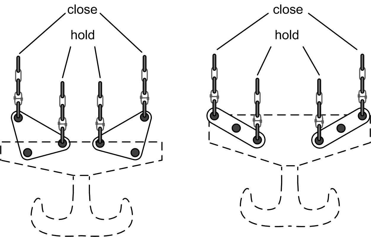
The following figure is a hook type with two variants of hooks with position difference between hold and close axes: 
The left hook uses a lever principle to distribute load depending on position difference between hold and close axes and the right one distributes the load evenly independent of the position difference. The left hook uses the shape of triangular connection blocks and the resulting variable lever arm length ratio to apply more load on close cables than on hold cables in the depicted position. The right hook applies the same load on both cables because the lever arm length ratio stays the same regardless of the position difference as long as both cables are straight. This makes the left hook well suited for operation in load sharing and the right one for position synchronization. When moving an unloaded hook, the torque may be too low for efficient load sharing. In this case it is possible to switch from position synchronization using the input i_xTrqShareEn when the torque value exceeds certain value. Switching between load sharing and positioning on the fly is possible as long as the synchronized positions are not far from positions in which the loads are in balance. |