Replacing the Motor or the Gearbox on the Rotational Axis
Overview
The use and application of the information contained herein require expertise in the design and programming of automated control systems. Only you, the user, machine builder or integrator, can be aware of all the conditions and factors present during installation and setup, operation, repair, and maintenance of the machine or process.
You must also consider any applicable standards and/or regulations with respect to grounding of all equipment. Verify compliance with any safety information, different electrical requirements, and normative standards that apply to your machine or process in the use of this equipment.
| DANGER | |
|---|---|
Procedure Overview
Perform the following procedures to replace the motor or the gearbox on the rotational axis:
Removing the Motor and the Gearbox
| NOTICE | |
|---|---|
|
Step |
Action |
|---|---|
|
1 |
Remove the telescopic axis as described in Replacing the Telescopic Axis. |
|
2 |
Remove the maintenance cover at the end of motor A. For further information on the position of the motor, refer to the detail drawing of the main body in Mechanical and Electrical Data. |
|
3 |
Disconnect the motor supply cable. For further information, observe the respective operating instructions of the motors:
|
|
4 |
Remove the hexagon cap from the ground connection at the motor. |
|
5 |
Disconnect the ground cable. |
|
6 |
Remove the four bolts (1) on the underside of the robot housing around the output shaft of the gearbox. 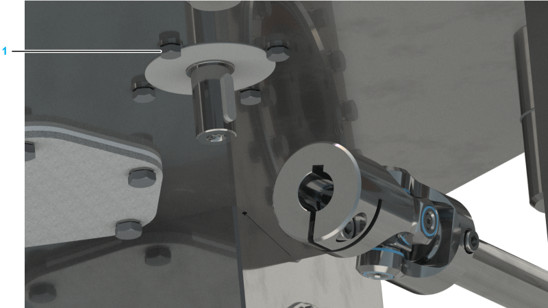
|
|
7 |
Carefully pull the motor and the gearbox upwards. |
|
8 |
Remove the motor and the gearbox from the robot housing. |
Removing the Motor from the Gearbox
|
Step |
Action |
|---|---|
|
1 |
Remove the O-ring (1) from the gearbox flange. 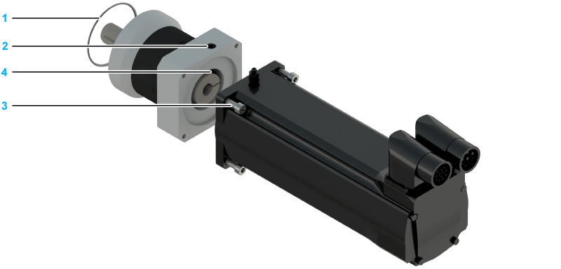
|
|
2 |
Remove the plug screw (2) from the gearbox flange. |
|
3 |
Remove the four screws (3) at the motor by means of which the motor is attached to the gearbox. |
|
4 |
Carefully rotate the motor until the screw (4) on the clamping ring appears in the aperture of the plug screw. |
|
5 |
Loosen this screw. |
|
6 |
Carefully remove the motor from the gearbox. |
Mounting the New Motor and/or the New Gearbox
|
Step |
Action |
|---|---|
|
1 |
Ensure that the gearbox and the housing are at the same temperature, as otherwise - in the case of a temperature difference - the gearbox may not fit into the aperture provided. |
|
2 |
Attach the motor to the gearbox according to the specifications of the manufacturer:
NOTE: Position the motor and the gearbox vertically during mounting if possible.
|
|
3 |
Insert the plug screw into the gearbox flange. |
|
4 |
Place a new O-ring to the gearbox. |
|
5 |
Attach the motor/gearbox combination in the orientation specified to the robot housing. Tightening torque: 3.5 Nm (31 lbf-in) For further information, refer to the detail drawing in Mechanical and Electrical Data. |
|
6 |
Use new sealing washers in order to maintain the leak tightness of the housing. |
| DANGER | |
|---|---|
| NOTICE | |
|---|---|
Cabling the Motor and the Gearbox
|
Step |
Action |
|---|---|
|
1 |
Attach the ground strap to the motor. Tightening torque: 2.5 Nm (22 lbf-in)
NOTE: When routing the cables, ensure that the grounding cap remains on the ground connection of the motors. The motor supply cable may become damaged by the thread of the ground strap attachment.
|
|
2 |
Put the hexagon cap on the ground connection at the motor. For further information, observe the respective operating instructions of the motors:
|
|
3 |
Attach the motor supply cables and lock them in position. |
|
4 |
Mount the telescopic axis as described in Replacing the Telescopic Axis. |
|
5 |
| DANGER | |
|---|---|
Calibrating the Robot and Closing the Housing
| NOTICE | |
|---|---|
|
Step |
Action |
|---|---|
|
1 |
Mount the telescopic axis as described in Replacing the Telescopic Axis. |
|
2 |
|
|
3 |
Mount the maintenance cover.
NOTE: Use a new seal in order to maintain the leak tightness of the housing.
For further information, refer to the detail drawing in Mechanical and Electrical Data. |
| WARNING | |
|---|---|