Cabling the VRKT•L••NC
Procedure Overview
Perform the following procedures to cable the robot:
Cabling the Robot
|
Step |
Action |
|---|---|
|
1 |
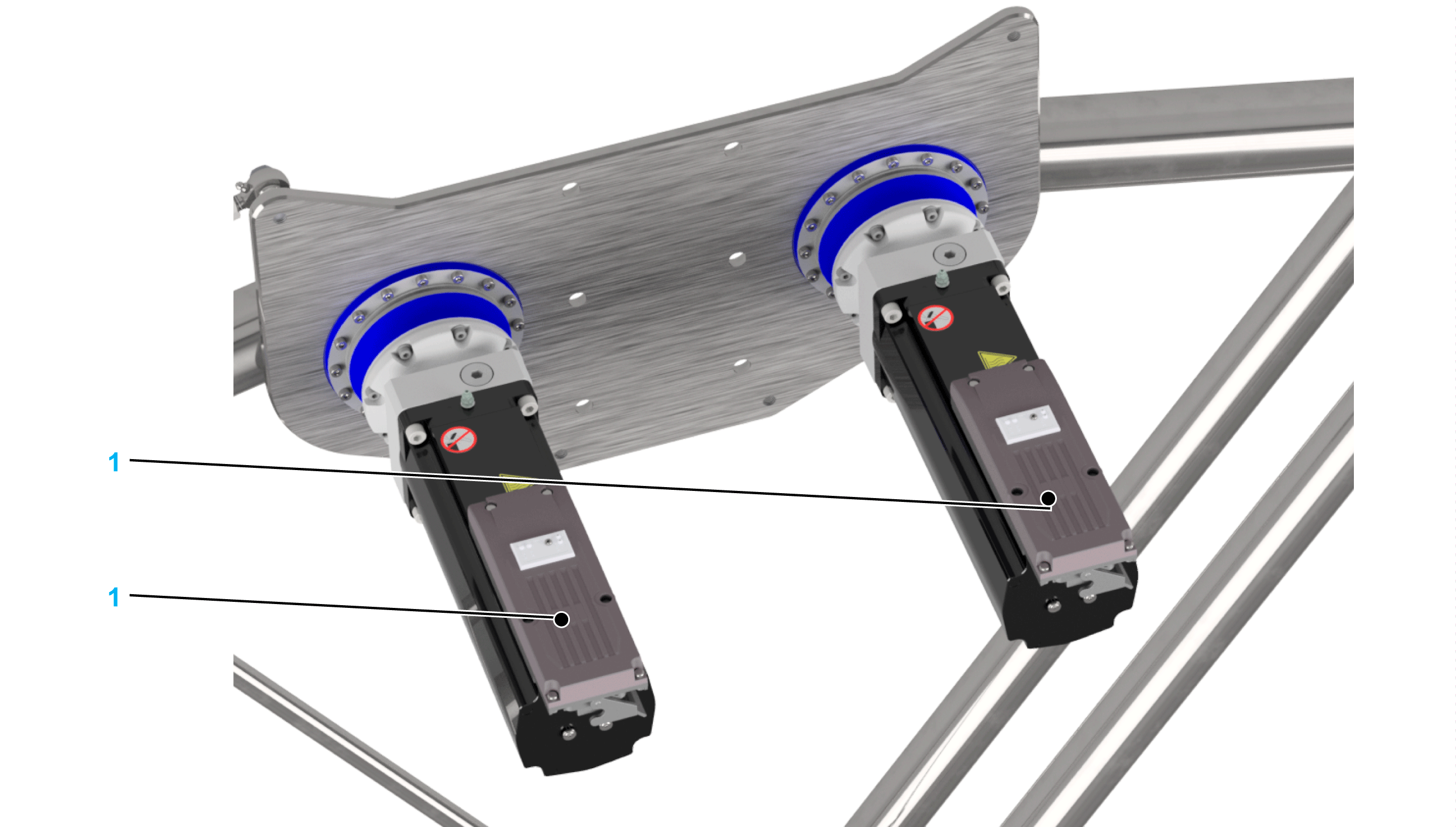
For each of the two main motors (1), feed one hybrid cable from a Distribution Box ILM62DB and connect them to the motors. 
NOTE: For equipment that you are supplying that is not described in the present document, consult the documentation for those products.
|
|
2 |
Verify the correct routing and fastening of the cables to help prevent any collision of cables and moving parts. |
| DANGER | |
|---|---|
For further information, refer to Lexium 62 Hardware Guide or Lexium 52 Hardware Guide.
Grounding the Robot
|
Step |
Action |
|---|---|
|
1 |
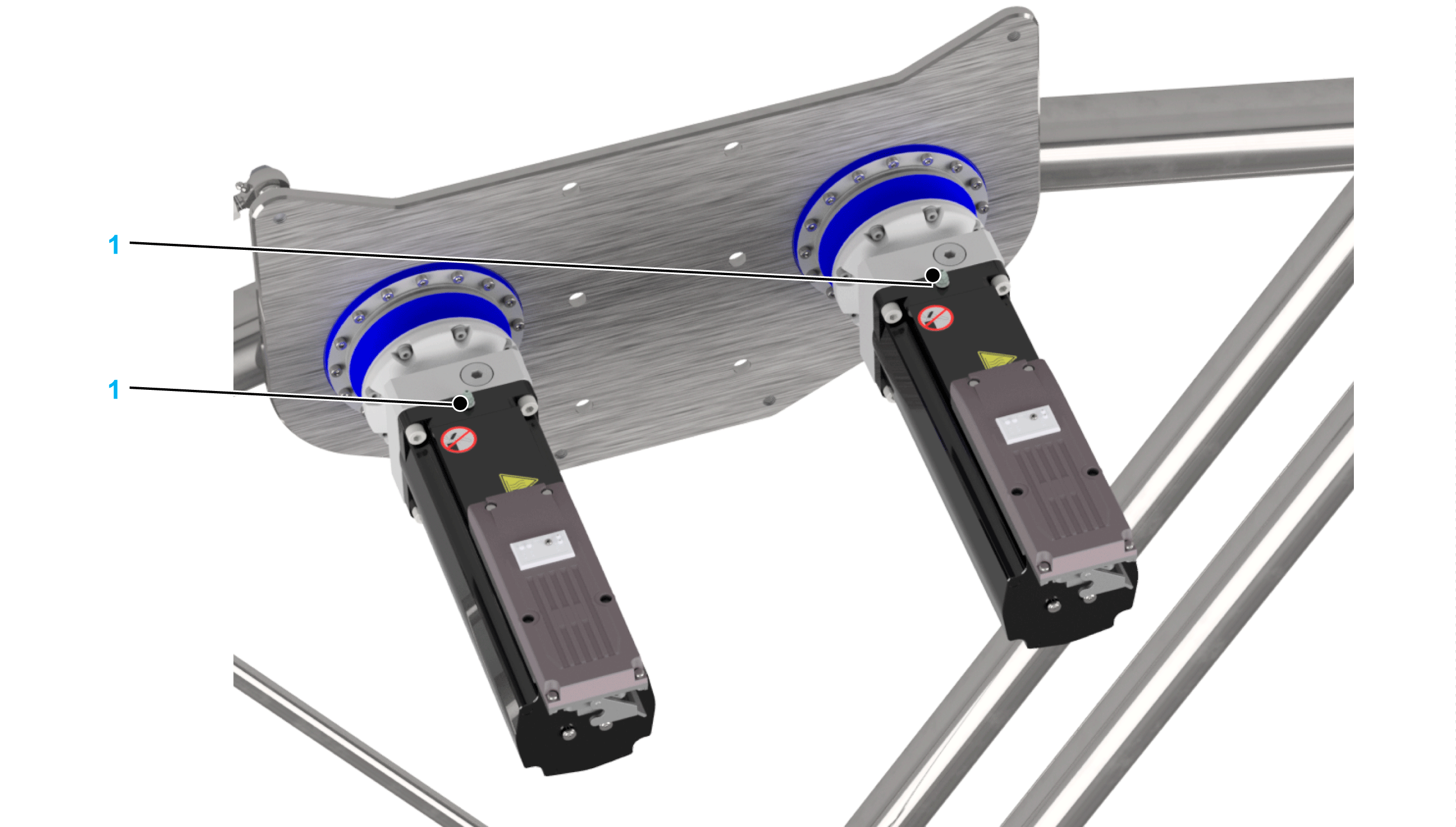
Fasten the ground cables to the ground connections (1) of the robot motors. The ground connections are marked with the following symbol: 
Tightening torque: 2.9 Nm (25.7 lbf-in) 
NOTE:
|
|
2 |
Verify the correct routing and fastening of the cables to help prevent any collision of cables and moving parts. |
| DANGER | |
|---|---|
Multipoint grounding is permissible if connections are made to an equipotential ground plane dimensioned to help avoid cable shield damage in the event of power system short-circuit currents.
Reducing Risks Around the Robot
|
Step |
Action |
|---|---|
|
1 |
Install external safety-related devices in accordance to local regulations and standards. |
|
2 |
When designing the safety-related devices, assume that the robot cannot be stopped by internal logic and must be stopped by the external safety-related devices.
NOTE: More information about the circuitry of emergency stop and additional protection elements is contained in the document Lexium 52 Hardware Guide, Lexium 62 Hardware Guide, or Lexium 62 ILM Hardware Guide.
|