Details on the application example
The application example is simplified and is intended to explain the functionality of the safety-related SF_SafeMotionControl function block. Therefore, this example is not intended as a practical safety solution implemented as shown and described in this document.
Only you, the user, machine builder or system integrator can be aware of all the conditions and factors realized in the design of your application for the machine. Therefore, only you can determine the automation equipment and the related safeties and interlocks which can be properly used, and validate such usage.
| WARNING | |
|---|---|
The function block may only be used in an actual application once a risk analysis has been carried out.
Details of the risk category/SIL/PL have not been included here, as classification is always based on the application in which the function block is used.
The use of the function block alone is not sufficient to execute the safety-related function according to the Cat./SIL/PL determined by the risk analysis. In conjunction with the safety-related I/O device used, additional measures must be taken to meet the requirements of the safety-related function. These include, for example, the appropriate wiring and parameterization of the inputs and outputs as well as measures to exclude (design out) errors that cannot be detected. For additional information, refer to the documentation provided with the safety-related I/O device used.
Refer to the notes in the User Manual on proper electrical connection of the Safety Module and the extension modules (e.g., connecting the emergency-stop control device).
Request of STO, SS1 and SLS by emergency-stop control device, light curtain and key switch
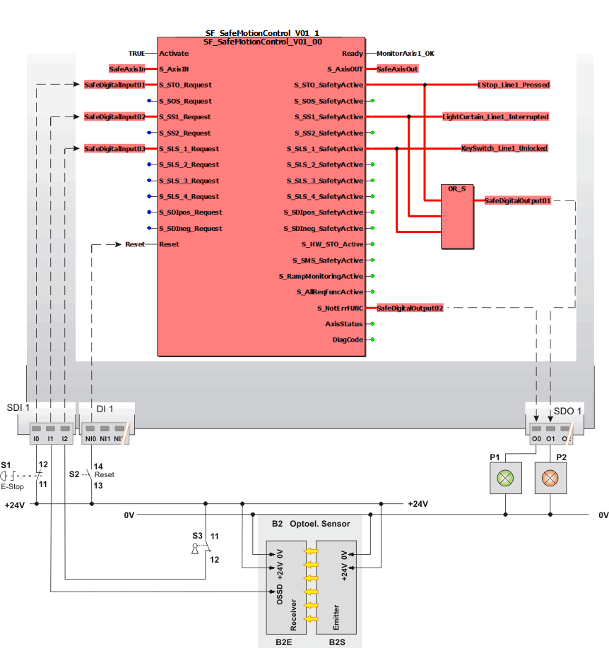
This example illustrates a simplified application of the SF_SafeMotionControl function block. It evaluates the status signals coming from three safety-related command devices and a manual reset device. According to these status signals, the Safety Logic Controller (SLC) requests the appropriate safety-related function(s) via the internally generated process data control word which his transmitted via the SERCOS bus to the Safety Module.
The Safety Module (and thus the drive), which is controlled by the standard (non-safety-related) controller, initiates the requested safety-related function and returns a status word to the SLC. By evaluating this status word, the SF_SafeMotionControl function block in turn monitors the state of the Safety Module and checks whether the safety-related functions have been activated as requested.
Input connections:
The Safety Logic Controller processes status signals coming from the following devices.
-
An emergency-stop control button S1 (single channel with N/C contact) is connected to terminal I0 of the TM5 safety-related input module SDI 1. This terminal is assigned to the global input variable SafeDigitalInput01 which is connected to the S_STO_Request for evaluation.
This means: a SAFEFALSE signal applied to this input by pressing the emergency-stop button requests the STO function.
-
An optoelectronic sensor (light curtain) B2 (single channel with N/C contact) is connected to terminal I1 of SDI 1. This terminal is assigned to the global input variable SafeDigitalInput02 which is connected to the S_SS1_Request for evaluation.
This means: a SAFEFALSE signal applied to this input by interrupting the light beam of the light curtain requests the SS1 function, thus stopping the machine.
-
A key switch S3 (single channel with N/C contact) is connected to terminal I2 of SDI 1. This terminal is assigned to the global input variable SafeDigitalInput03 which is connected to the S_SLS_1_Request for evaluation.
This means: a SAFEFALSE signal applied to this input by unlocking the key switch requests the SLS1 function, thus reducing/limiting the speed.
-
The SafeAxisIn data item, provided by the Safety Module is connected to the S_AxisIN input. Its value is determined and provided by the Safety Module which is controlling the axis.
-
To reset error states and to remove the start-up/restart inhibit, the S2 reset button is connected to input NI0 of the standard extension device DI 1. This terminal is assigned to the global input variable Reset which is connected to the Reset input of the function block.
Output connections:
-
The status outputs of the used safety-related functions (S_STO_SafetyActive, S_SS1_SafetyActive and S_SLS_1_SafetyActive) write symbolic variables which can be evaluated in the safety-related application program.
-
If any of the safety-related functions is activated, the red signaling lamp P2 connected to output O1 of the safety-related extension device SDO 1 lights up signaling the request and successful activation.
-
If each requested safety-related function is activated correctly, the green signaling lamp P1 connected to output O0 of the safety-related extension device SDO 1 lights up signaling the correct function.
-
The SafeAxisOut data item provided by the Safety Module is connected to the S_AxisOUT output. Its value is determined and provided by the Safety Module which is controlling the axis.
|
S1 |
Emergency-stop |
|
S2 |
Reset |
|
S3 |
Key switch with N/C contacts for positive opening operation (SAFETRUE if locked). |
|
B2 |
Single-channel light grid (B2S = optoelectronic transmitter, B2E = optoelectronic receiver) |