Additional signal sequence diagram
Temporary intermediate states are not illustrated in the signal sequence diagram. Only typical input signal combinations are illustrated in the diagram. Other signal combinations are possible.
The most significant areas within the signal sequence diagram are highlighted in color.
Refer also to the diagram found in the overview for this function block.
The signal sequence diagrams in this documentation possibly omit particular diagnostic codes. For example, a diagnostic code is possibly not shown if the related function block state is a temporary transition state and only active for one cycle of the Safety Logic Controller.
Only typical input signal combinations are illustrated. Other signal combinations are possible.
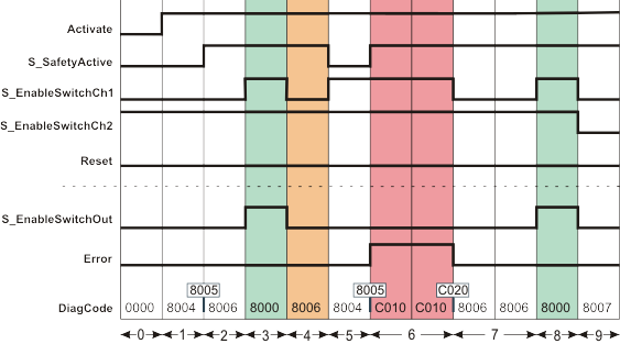
No restart inhibit after invalid signal sequence (S_AutoReset = SAFETRUE)
|
0 |
The function block is not yet activated (Activate = FALSE). As a result, all outputs are FALSE or SAFEFALSE. |
|
1 |
The function block is activated (Activate = TRUE). Switching stage 1 is present (input S_EnableSwitchCh1 = SAFEFALSE, input S_EnableSwitchCh2 = SAFETRUE). The operating mode is not active (S_SafetyActive = SAFEFALSE). |
|
2 |
The operating mode is active (S_SafetyActive = SAFETRUE). |
|
3 |
In the operating mode, the switching stage changes from stage 1 to stage 2 (input S_EnableSwitchCh2 and input S_EnableSwitchCh1 = SAFETRUE) and the S_EnableSwitchOut output becomes SAFETRUE. |
|
4 |
Change from switching stage 2 back to switching stage 1 (signal at S_EnableSwitchCh1 becomes SAFEFALSE); the S_EnableSwitchOut output becomes SAFEFALSE. |
|
5 |
Change from switching stage 1 to switching stage 2 (S_EnableSwitchCh1 becomes SAFETRUE again). However, as the operating mode is no longer active (S_SafetyActive = SAFEFALSE), the S_EnableSwitchOut output remains SAFEFALSE. |
|
6 |
The operating mode is now active again (S_SafetyActive = SAFETRUE) and the function block initially expects switching stage 1. However, as switching stage 2 is present at this time (S_EnableSwitchCh1 and S_EnableSwitchCh2 = SAFETRUE), the Error output switches to TRUE. |
|
7 |
Change from switching stage 2 back to switching stage 1 (S_EnableSwitchCh1 becomes SAFEFALSE). As the restart inhibit is not active (S_AutoReset = SAFETRUE), the Error output immediately switches to FALSE again. |
|
8 |
In the operating mode, the switching stage changes from stage 1 to stage 2 (input S_EnableSwitchCh2 and input S_EnableSwitchCh1 = SAFETRUE) and the S_EnableSwitchOut output becomes SAFETRUE. |
|
9 |
Switching stage 3 is present (S_EnableSwitchCh1 and S_EnableSwitchCh2 = SAFEFALSE), the S_EnableSwitchOut output becomes SAFEFALSE. |