4-Axis Palletizer Kinematics
The 4-axis palletizer kinematics is a general robot type that is used frequently for palletizing tasks. The kinematics are provided with four controlled rotary axes (marked in red) and a fifth mechanical rotary axis (marked in gray). The POUs SMC_Trafo_4AxisPalletizer and SMC_TrafoF_4AxisPalletizer implement its forward and inverse transformation.
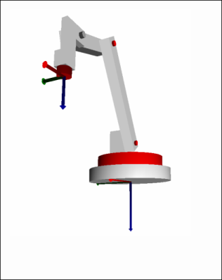
The Cartesian coordinate system is the basis for the palletizer. The Z axis points downwards perpendicularly and the X axis forwards, which means in the direction that the arm points in the zero direction of the axes. The origin of the Cartesian coordinate system is the intersection of the joint axis 1 and the underside of the robot.
Definition of axes
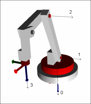
The following image shows the rotational direction of the four axes. The black arrows run along the joint axis. The rotational direction is determined according to the right-hand rule: If the thumb of the right hand points downwards along the arrow, then the positive rotational direction is in the direction of the slightly curved finger. For example, when viewed from above, the positive rotational direction of axis 0 is clockwise, while axes 1 and 2 tilt forwards for positive rotation.
Value ranges of the axes:
-
Axis 0: ]-180°, 180°[
-
Axis 1: [-90°, 90°]
-
Axis 2: [-180°, 90[
-
Axis 3: Unrestricted; the range can also be greater than 360°.
Zero position and dimensions
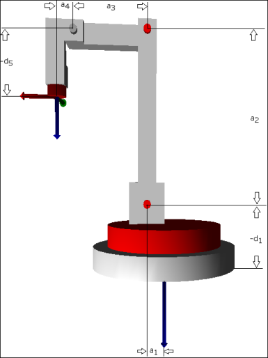
The picture aside shows the kinematics in zero position of all axes: In the zero position, the axes of the tool coordinate system run parallel to those of the machine coordinate system. Specify the indicated dimensions in the configuration structure SMC_TrafoConfig_4AxisPalletizer. Also specify all a_i with positive signs and all d_i with negative signs. The names of the parameters are according to the Denavit-Hartenberg convention.
Programming in G code
The position of the gripper is controlled with X, Y, and Z. The rotation of the gripper on the vertical is controlled by the additional axis C. The angles are specified in degrees.