Visualization Element 'Trace'
Symbol:
Tag: Special Controls
The element displays the graphical curve of variable values. In addition, variables can be configured to control the view.
See also
Element properties
|
Element name |
Example: |
|
Data Source |
Location where the trace data is buffered.
|
|
Application |
Application where data was recorded.
Requirement: A remote data source (not <local application>) is referenced in the Data source property. |
|
Type of element |
Trace |
|
Trace |
|
See also
Element property 'Position'
The position defines the location and size of the element in the visualization window. This is based on the Cartesian coordinate system. The origin is located at the upper left corner of the window. The positive horizontal x-axis runs to the right. The positive vertical y-axis runs downwards.
|
X |
The x-coordinate of the upper left corner of the element Specified in pixels
Example: |
|
Y |
The y-coordinate of the upper left corner of the element Specified in pixels
Example: |
|
Width |
Specified in pixels
Example: |
|
Height |
Specified in pixels
Example: |
|
Tip: You can change the values in X, Y, Width, and Height by dragging the corresponding symbols |
|
|
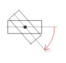
Angle |
Static angle of rotation (in degrees)
Example: The element is displayed rotated in the editor. The point of rotation is the center of the element. A positive value rotates clockwise.
Tip: You can change the value in the editor by focusing the element to the handle. When the cursor is displayed as a rotating arrow
Note: If a dynamic angle of rotation is also configured in the property , then the static and dynamic angles of rotation are added in runtime mode. The static angle of rotation acts as an offset. |
 (1): Handle
See also
|
Show cursor |
|
|
Overwrite existing trace on PLC |
|
|
Number format |
Number format of values in the tooltip in printf syntax (example: %d, %5.2f). |
Element property 'Control variables'
The control variables are assigned automatically when you click Insert elements for controlling Trace.
|
Reset Trigger |
Variable (
Standard control variable:
|
|
Start Trace |
Variable (
Standard control variable:
|
|
Stop Trace |
Variable (
Standard control variable:
|
|
Save Trace to a file |
|
|
Save Trace |
Variable (
Standard control variable:
|
|
File name |
Variable (
Standard control variable: |
|
Load trace from file |
|
|
Load Trace |
Variable (
Standard control variable:
Note: A trace configuration can be loaded from a file only under special circumstances. The file must have been created with exactly the same (running) application with which it will then be loaded. The consequence of changing the running application (for example by downloading again) is that a file which was previously created from the application cannot no longer be read into the application. Even external manual changes to the file can cause this. You should edit only those configuration settings that have an effect on displaying the variables. If you change variable definitions directly in the file (for example by replacing variable x with v y), then the file cannot be loaded. |
|
File name |
Variable (
Standard variable: |
See also
Element property 'Center'
The properties contain fixed values for the coordinates of the point of rotation. This point of rotation is shown as the ![]() symbol. The point is used as the center for rotating and scaling.
symbol. The point is used as the center for rotating and scaling.
You can also change the values by dragging the symbols (![]() ) to other positions in the editor.
) to other positions in the editor.
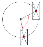
Element property 'Absolute movement'
The properties contain IEC variables for controlling the position of the element dynamically. The reference point is the upper left corner of the element. In runtime mode, the entire element is moved.
|
Movement |
||
|
X |
Variable (numeric data type). Defines the X position (in pixels).
Example: Increasing this value in runtime mode moves the element to the right. |
|
|
Y |
Variable (numeric data type). Defines the Y position (in pixels).
Example: Increasing this value in runtime mode moves the element downwards. |
|
|
Rotation |
Variable (numeric data type). Defines the angle of rotation (in degrees).
Example:
The midpoint of the element rotates at the Center point. This rotation point is shown as the In runtime mode, the alignment of the element remains the same with respect to the coordinate system of the visualization. Increasing the value rotates the element to the right. |
|
|
Interior rotation |
Variable (numeric data type). Defines the angle of rotation (in degrees).
Example: In runtime mode, the element rotates about the point of rotation specified in Center according to the value of the variable. In addition, the alignment of the element rotates according to the coordinate system of the visualization. Increasing the value in the code rotates clockwise.
The rotation point is shown as the Note: If a static angle of rotation is specified in the property, then the static angle of rotation is added to the variable angle of rotation (offset) when the visualization is executed. |
|
You can link the variables to a unit conversion.
The X, Y, Rotation, and Interior rotation properties are supported by the "Client Animation" functionality.
See also
Element property 'State variables'
The variables control the element behavior dynamically.
|
Invisible |
Variable (
|
The Invisible property is supported by the "Client Animation" functionality.
See also
These properties are available only when you have selected the Preview: Support client animations and overlay of native elements option in the Visualization Manager.
|
Animation duration |
Defines the duration (in milliseconds) in which the element runs an animation
Animatable properties
The animated movement is executed when at least one value of an animatable property has changed. The movement then executed is not jerky, but is smooth within the specified animation duration. The visualization element travels to the specified position while rotating dynamically. The transitions are smooth. |
|
Move to foreground |
Moves the visualization element to the foreground
Variable (
Example:
|
See also
Element property 'Access rights'
Requirement: User management is set up for the visualization.
|
Access rights |
Opens the Access rights dialog. There you can edit the access privileges for the element. Status messages:
|
See also