Visualizing Alarm Management
In CODESYS, the alarm management is a powerful object for creating and managing alarms. You can group alarms and set the acknowledgment behavior individually. The alarm display in the visualization can also be customized.
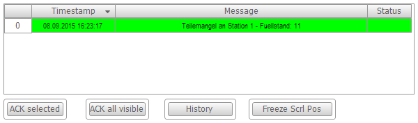
The Alarm Table and Alarm Banner visualization elements are available for displaying and processing alarms. The alarm table lists the alarm texts. The alarm banner is a simplified version of the alarm table. It visualizes a single alarm only. However, by adding scroll elements you can allow for switching the display from one active alarm to another active alarm.
See also
Creating an alarm table
Requirement: In your project, alarms are defined in alarm groups and they are assigned to an alarm class. The following instructions are based on the example that is described in the "Configuring Alarm Management" chapter.
-
Open the visualization editor.
-
Drag the Alarm Table element from the Alarm Manager group to the visualization editor.
⇒ The Alarm Table visualization element is visible in the editor.
-
In the Alarm configuration / Alarm groups property, define the alarm groups that you want to visualize. Click into the value field.
⇒ The Select Alarm Group dialog opens.
-
Clear the All check box and select the PartsDeficit alarm group. Add the group to the selected alarm groups by clicking the
 button.
-
In the Alarm configuration / Alarm classes property, define the alarm classes that you want to visualize. Click into the value field.
⇒ The Select Alarm Class dialog opens.
-
Clear the All check box and select the PartsDeficit alarm class. Add the alarm class to the selected alarm classes by clicking the
button.
-
Add an additional column. Click the Columns / Create new button.
⇒ CODESYS adds the column [2] to the properties. The Symbol column is added to the table.
-
Select data type State for column [2].
⇒ The default column heading State is shown in the table.
-
Name the Column heading column "Status".
-
Specify the appearance of the selected table cell. Set the Selection / Selection color to Green.
-
In the Control variables / Confirm selection property, specify the variable
bQuitAlarmfor confirming messages. -
Adjust the other properties to your requirements. See the "Alarm Table" visualization element for a complete description of the properties.
See also
Inserting elements for acknowledging alarms
In CODESYS, predefined buttons are available for controlling the alarms in an alarm table.
Requirement: An Alarm Table element exists in the visualization.
-
Select the visualization element in the editor.
-
Click .
⇒ The Alarm Table Wizard dialog opens.
-
Click OK to accept all settings.
⇒ Four buttons are added for controlling the alarm table.
See also
Creating an alarm banner
Requirement: In your project, alarms are defined in alarm groups and they are assigned to an alarm class. The following instructions are based on the example that is described in the "Configuring Alarm Management" chapter.
The alarm banner displays an active alarm in online mode. If there are multiple active alarms, filtering takes place by means of the filter criteria set in the alarm banner (newest for filter criterion "Priority" and most important for filter criterion "Newest"). See the instructions below for adding scroll elements in order to switch the display between multiple alarms.
-
Open the visualization editor.
-
Drag the Alarm Banner element from the Alarm Manager group to the visualization editor.
⇒ The Alarm Banner visualization element is visible in the editor.
-
In the Alarm configuration / Alarm groups property, define the alarm groups that you want to visualize. Click into the value field.
⇒ The Select Alarm Group dialog opens.
-
Clear the All check box and select the PartsDeficit alarm group. Add the group to the selected alarm groups by clicking the
button.
-
In the Alarm configuration / Alarm classes property, define the alarm classes that you want to visualize. Click into the value field.
⇒ The Select Alarm Class dialog opens.
-
Clear the All check box and select the PartsDeficit alarm class. Add the alarm class to the selected alarm classes by clicking the
button.
-
Set the Alarm configuration / Filter criterion property to Newest.
⇒ In online mode, the newest alarm message is always shown.
-
Add an additional column. Click the Columns / Create new button.
⇒ CODESYS adds the column [2] to the properties. The Symbol column is added to the table.
-
Select data type State for column [2].
⇒ The default column heading State is shown in the table.
-
In the Confirmation variable property, specify the variable
bQuitAlarmfor confirming messages.
See also
Adding elements for scrolling the active alarms
Elements can be added to an alarm banner for switching the display between the individual active alarms. You can control the scrolling with visu-local variables or application variables.
-
Select the added "Alarm Banner" visualization element. In the context menu, click Insert Elements for Scrolling Alarms.
⇒ The Alarm Banner Wizard opens.
-
Select the element type for the scroll elements: Button or Rectangle.
-
Activate the action(s) for which a control should be inserted: Scroll to next alarm, Scroll to previous alarm.
-
Specify a Boolean variable that gets the value
TRUEwhen multiple active alarms are present. If you have already configured a project variable in the element properties, then it is also specified here in the wizard. Otherwise CODESYS automatically creates the visu-local variable xMultipleAlarmsActive. -
In the next step, check the configuration of the element properties of the extended alarm banner.
-
Select the alarm banner element and look at the section Handling of multiple active alarms in the Properties view. You have two options:
-
Option 1: The display should switch automatically. Activate the Switch automatically property.
⇒ Now, in Every N seconds you define the time interval after which the display in the alarm banner in online mode should switch to the next alarm.
-
Option 2: The display should be controlled by means of the application. Deactivate the Switch automatically property.
⇒ Switching between the active alarms can be controlled by two variables. By default,
xNextandxPrevare created for scrolling to the next or previous alarm. You can replace these variables with custom your own defined application variables.
Filter alarm events by the contents of the latch variable
Filtering by the contents of a latch variable can be useful when there are a lot of alarm events displayed. If the latch variable assigned to an alarm in the alarm group definition contains, for example, the error number or the name of a device instance, then you can filter the alarms in the visualization by it.
For this purpose, you configure an input option in the alarm visualization for the contents of the latch variable to be filtered by. For example, insert an input field which writes to the variable that is specified in the Alarm configuration - Filter by latch 1 - Filter variable property of the configuration of the Alarm Table element or Alarm Banner element.
In addition, you configure an input option for the type of filtering. The type determines whether a numeric value (typed literal, LINT literal) or the string value of the latch variable is used for filtering. Filtering can also be switched off by means of type setting 0. For example, in the visualization, insert another input field which writes to the variable that is specified in the Filter type property of the configuration of the alarm table or alarm banner.
For more information, see the "Alarm Filter Latch Example" sample project in the CODESYS Store .
Displaying alarm events for a specific time period
In many cases, it is known in which time period the problems occurred and these were recorded as alarms. Then it is often useful to display only those alarms that occurred within the specified time period. The important information is displayed optimally and found more quickly.
To do this, in the alarm visualization, you configure two input options for variables, which are located in the configuration of the Alarm Table or Alarm Banner elements, in the Alarm configuration - Filter variable, from and Filter variable, to property. Moreover, you configure an input field for the variable that enables or disables the filtering. This variable is located in the configuration of the Alarm Table or Alarm Banner elements, in the Alarm configuration - Filter type property.