Addressing
Introduction
The TM5 backplane of bus bases, which holds the individual I/O modules together, is auto-addressing. It is usually not necessary to set the address setting numbers.
However, in certain cases, it may be necessary to define specific slices or potential groups at fixed addresses, regardless of the preceding modules in the backplane. For this purpose, there are bus bases in the TM5 System with rotary switches, which allow you to set the address of an individual slice. All subsequent slices refer to this offset and are again automatically addressed from this point forward.
Addressing Principle
In the TM5 System, the address setting number begins at 1 and is the address number of the Interface Power Distribution Module (IPDM) of the distributed configuration.
The following modules and expansion modules addresses are assigned according to their positions in the TM5 backplane (+1 regarding the left preceding module address).
Bus Bases with Address Setting
The following table gives you the references of the bus bases with address setting:
|
References |
Description |
Color |
|---|---|---|
|
TM5ACBM05R |
24 Vdc / 24 Vdc I/O power segment left isolated with address setting |
Gray |
|
TM5ACBM15 |
24 Vdc / 24 Vdc I/O power segment pass-through with address setting |
White |
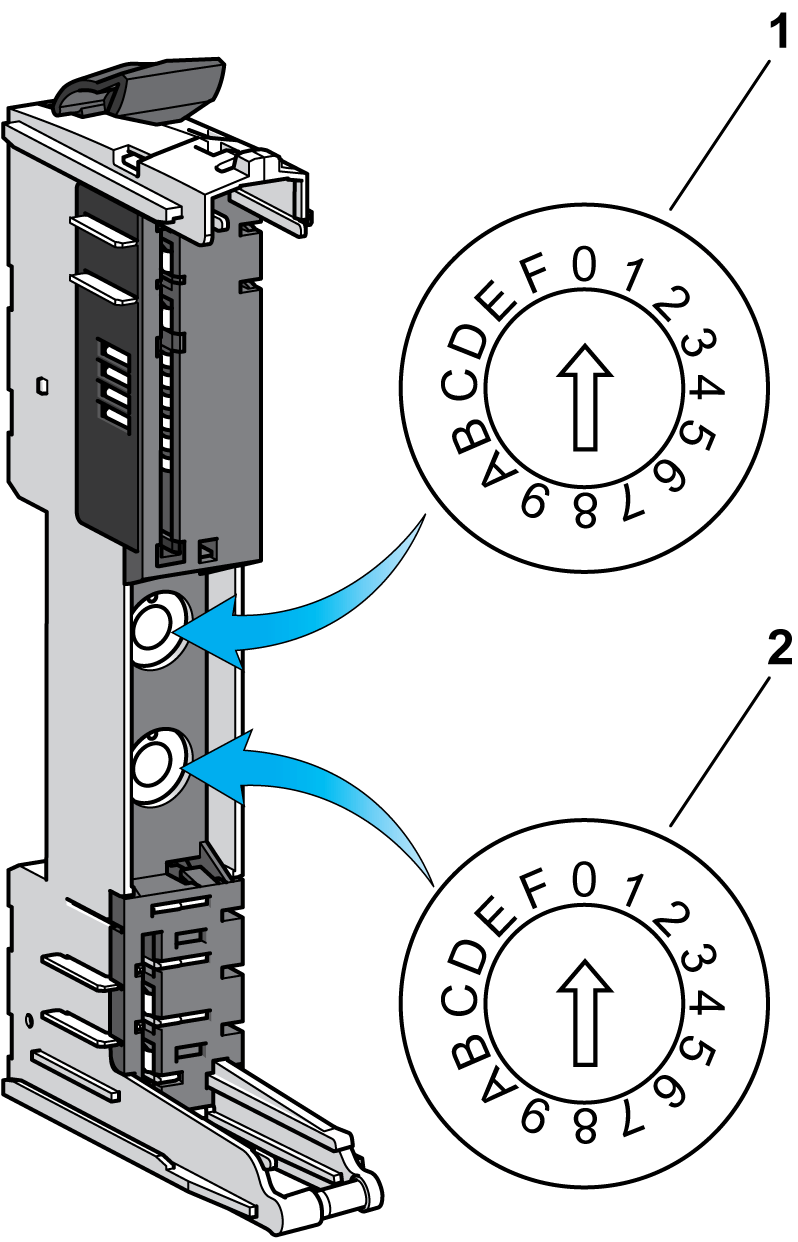
Address Setting Rotary Switches

1 x16
2 x1
The address of the slice is set using the address setting rotary switches (01 - FD hex).
The address setting 00 hex causes automatic assignment of the address of the expansion module.
| WARNING | |
|---|---|
Set the rotary switches before installing the bus base on the DIN rail and making a connection to the other components of your TM5 system. If the bus base is already installed before its address has been set, then remove all power to your TM5 system before setting the address.
| DANGER | |
|---|---|
You must use a flat-head screwdriver of the size noted below to turn the rotary address selection switches.

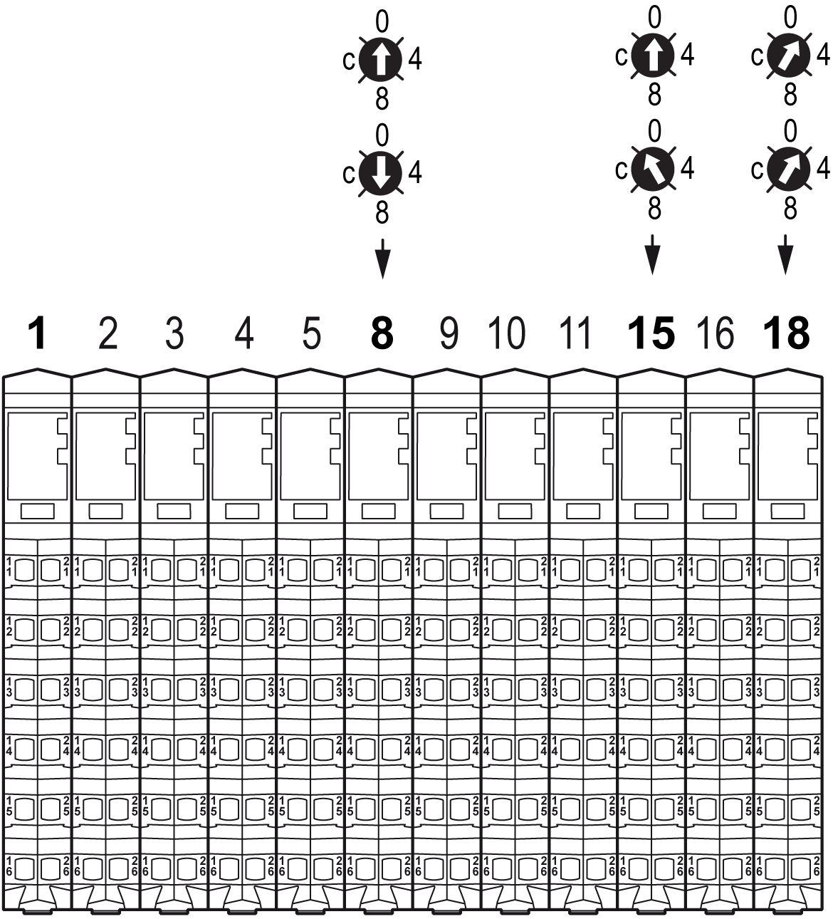
Example
The example below demonstrates the automatic addressing of the slices up to the point of a bus base with an address setting rotary switch. This bus base forces the address for the slice, in the example, to 8. From that point, the automatic sequential addressing continues until the next bus base with an address setting rotary switch is encountered.
