Safety Terminal Block Presentation
TM5ACTB52FS Features
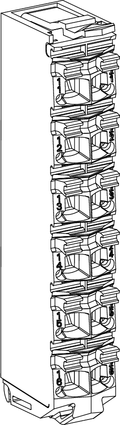
The safety-related modules and the Safety Logic Controllers are wired by means of the TM5ACTB52FS Safety terminal block:
|
Features |
|
|---|---|
|
Type of terminal block |
12-pin, safety coded terminal block |
|
Features |
|
Ordering Information
The following figure presents the TM5ACTB52FS Safety terminal block:
The following table presents the reference for the Safety terminal block:
|
Reference |
Description |
Color |
|---|---|---|
|
TM5ACTB52FS |
24 Vdc / 230 Vac, 12-pin terminal block for safety-related modules and Safety Logic Controllers, safety coded |
red |
| DANGER | |
|---|---|
Characteristics
This section describes the characteristics of the TM5ACTB52FS Safety terminal block, you can also refer to TM5 Environmental Characteristics.
| DANGER | |
|---|---|
| WARNING | |
|---|---|
| WARNING | |
|---|---|
The following table lists the characteristics of the TM5ACTB52FS:
|
Characteristics |
||
|---|---|---|
|
Type of terminal block |
Push-in terminal block |
|
|
Distance between contacts |
left - right |
4.2 mm / 0.16 in |
|
above - below |
10.96 mm / 0.43 in |
|
|
Contact resistance |
≤ 5 mΩ |
|
|
Maximum current carrying capacity of the connector |
10 A / contact
NOTE: The electrical characteristics of the individual modules must be respected.
|
|
|
Connection cross section |
solid wire |
0.08 mm2 ... 2.5 mm2 / AWG 28 ... 14 |
|
multi-wire |
0.25 mm2 ... 2.5 mm2/ AWG 24 ... 14 |
|
|
with wire cable ends |
0.25 mm2 ... 1.5 mm2 / AWG 24 ... 16 |
|
|
- |
Up to 2x 0.75 mm2 (AWG 2 x 24 ... 2 x 18) with double wire cable ends |
|
|
Cable type |
Copper wires only |
|
| DANGER | |
|---|---|