Connection Examples
Overview
The following sections present typical connection examples, which only represent one of the possible wiring methods.
Connecting Single-Channel Sensors with Contacts
The following graphic presents the single-channel connection of sensors with contacts:
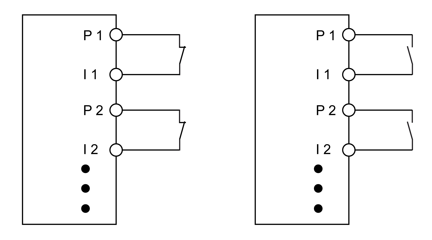
P Test (pulse) output
I Input
Single-channel sensors with contacts are a simple connection. With this connection, the module corresponds to Category 3 according to EN ISO 13849. This only applies to the module and not to the wiring presented.
| WARNING | |
|---|---|
The test output issues a specific signal that helps detect wiring issues, such as a short circuit of the +24 V, COM, or other signal channels.
| WARNING | |
|---|---|
This wiring provides the following error detection when PulseMode=internal:
|
Potential error |
Error detection |
|
|---|---|---|
|
Open |
Closed |
|
|
Ground error on test (pulse) output |
Detected |
Detected |
|
Test (pulse) output short-circuit with 24 V |
Detected |
Detected |
|
Short circuit between test (pulse) output and other test (pulse) signal |
Detected |
Detected |
|
Ground error on signal input |
Not detected |
Detected |
|
Signal input short-circuit with 24 V |
Detected |
Detected |
|
Short circuit between signal input and other test (pulse) signal |
Detected |
Detected |
|
Short circuit between test (pulse) output and signal input |
Not detected |
Not detected |
|
Broken wire |
Not detected |
Not detected |
Make all necessary repairs in a timely manner if an error occurs because subsequent errors could create a hazardous situation.
| WARNING | |
|---|---|
PulseMode=internal, the test pulses have a low phase of about 300 µs. This low phase is designed such that no additional decline in total response time can occur in the system. However, issues can arise with the factory setting clock form when line lengths are used that exceed the maximum cable length (refer to General Characteristics). In such cases, the external clock form can also be used for normal, electro-mechanic contacts. Keep in mind, however, that the effectiveness of error detection is reduced, and the total response time is increased.
Connecting Two-Channel Sensors with Contacts
The following graphic presents the two-channel sensors with contacts:
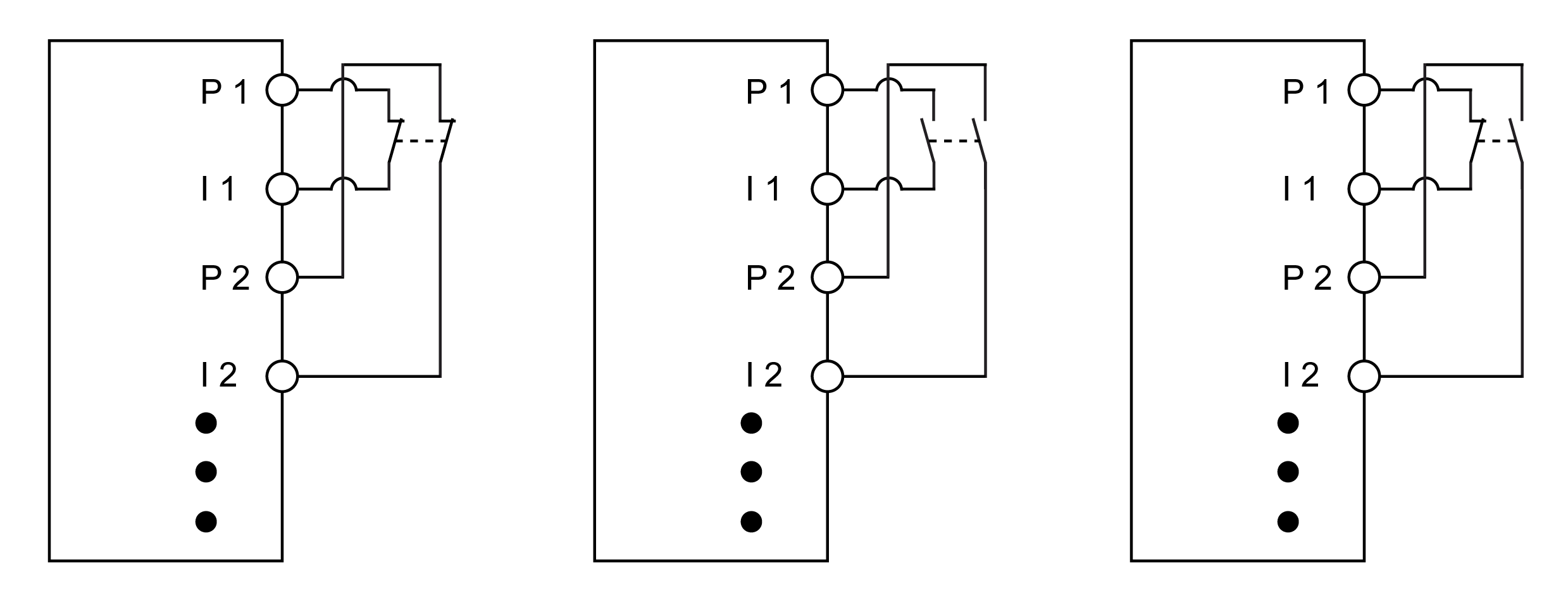
P Test (pulse) output
I Input
-
Two-channel sensors with contacts can be connected directly to a safety-related digital input module.
-
The two-channel evaluation is handled directly by the module.
With this connection, the module corresponds to Category 4 according to EN ISO 13849. This only applies only to the module and not to the wiring presented.
| WARNING | |
|---|---|
The test output issues a specific signal that helps detect wiring issues, such as a short circuit of the +24 V, COM, or other signal channels.
On module types that do not have these LED indicators, errors detected by the two-channel monitoring are indicated by the LED indicator for the respective channel flashing red.
| WARNING | |
|---|---|
This wiring provides the following error detection when PulseMode=internal in combination with two-channel evaluation in the module or in the Machine Expert - Safety software:
|
Potential error |
Error detection |
|
|---|---|---|
|
Open |
Closed |
|
|
Ground error on test (pulse) output |
Detected |
Detected |
|
Test (pulse) output short-circuit with 24 V |
Detected |
Detected |
|
Short circuit between test (pulse) output and other test (pulse) signal |
Detected |
Detected |
|
Ground error on signal input |
Not detected |
Detected |
|
Signal input short-circuit with 24 V |
Detected |
Detected |
|
Short circuit between signal input and other test (pulse) signal |
Detected |
Detected |
|
Short circuit between test (pulse) output and signal input |
Detected 1) |
Not detected |
|
Broken wire |
Not detected |
Detected 1) |
|
1) Two-channel evaluation of the module |
||
Make all necessary repairs in a timely manner if an error occurs because subsequent errors could create a hazardous situation.
| WARNING | |
|---|---|
PulseMode=internal, the test pulses have a low phase of about 300 µs. This low phase is designed such that no additional decline in total response time can occur in the system. However, issues can arise with the factory setting clock form when line lengths are used that exceed the maximum cable length (refer to General Characteristics). In such cases, the external clock form can also be used for normal, electro-mechanic contacts. Keep in mind, however, that the effectiveness of error detection is reduced, and the total response time is increased.
Connecting Multi-Channel Sensors with Contacts
The following graphic presents the connection of multi-channel, electro-mechanical switches:
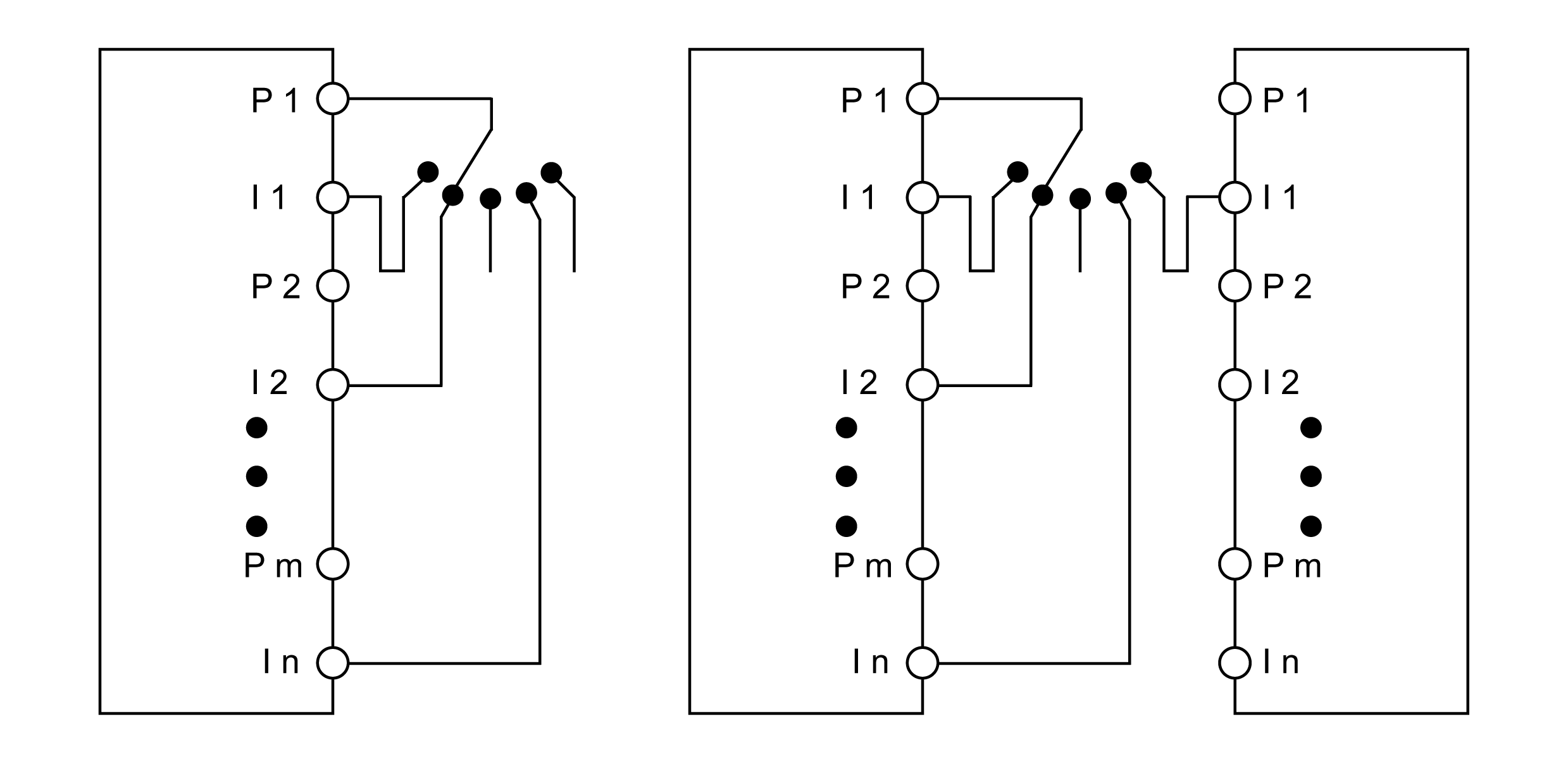
P Test (pulse) output
I Input
Multi-channel switches (operating mode switches, switching devices with shifting capability) may be connected to several safety-related, digital input devices. All inputs must be configured to use the same test (pulse) rate coming from the same test (pulse) source. The modules that are not using an internal test source must be configured to use an external test source (PulseMode=external). That is to say, a test source external to itself, but from another TM5/TM7 module as you can see in the left-most wiring diagram.
The modules that use an internal test (pulse) source must be configured to use an internal test source (PulseMode=internal).
The difference between using a single module and multiple modules is the system response time. In the case of multiple modules, test (pulse) rate must be set to a wave form of 4 ms low phase. In the case of a single module, you can set a wave form of 300 µs low phase.
| WARNING | |
|---|---|
When connecting multi-channel sensors with contacts, the multi-channel analysis must be executed in the safety-related application (PLCopen function block ModeSelector).
The status of the connected sensors is indicated by channel-specific LED indicators. The LED indicators OO and OC are not relevant when using multi-channel selectors.
| WARNING | |
|---|---|
This wiring provides the following error detection when PulseMode=external:
|
Potential error |
Error detection |
|---|---|
|
Ground error on test (pulse) output |
Detected |
|
Test (pulse) output short-circuit with 24 V |
Detected |
|
Short circuit between test (pulse) output and other test (pulse) signal |
Detected 1) |
|
Ground error on signal input (active signal) |
Detected 1) |
|
Ground error on signal input (inactive signal) |
Not detected |
|
Signal input short-circuit with 24 V |
Detected |
|
Short circuit between signal input and other test (pulse) signal |
Detected 1) |
|
Short circuit between test (pulse) output and signal input (active signal) |
Not detected |
|
Broken wire (active signal) |
Detected 1) |
|
Short circuit between test (pulse) output and signal input (input signal) |
Detected 1) |
|
Broken wire (inactive signal) |
Not detected |
|
1) Detected in the application by PLCopen function block |
|
This wiring provides the following error detection when PulseMode=internal:
|
Potential error |
Error detection |
|
|---|---|---|
|
Open |
Closed |
|
|
Ground error on test (pulse) output |
Detected |
Detected |
|
Test (pulse) output short-circuit with 24 V |
Detected |
Detected |
|
Short circuit between test (pulse) output and other test (pulse) signal |
Detected |
Detected |
|
Ground error on signal input |
Not detected |
Detected |
|
Signal input short-circuit with 24 V |
Detected |
Detected |
|
Short circuit between signal input and other test (pulse) signal |
Detected |
Detected |
|
Short circuit between test (pulse) output and signal input |
Not detected |
Not detected |
|
Broken wire |
Not detected |
Not detected |
Make all necessary repairs in a timely manner if an error occurs because subsequent errors could create a hazardous situation.
| WARNING | |
|---|---|
PulseMode=internal, the test pulses have a low phase of about 300 µs. This low phase is designed such that no additional decline in total response time can occur in the system. However, issues can arise with the factory setting clock form when line lengths are used that exceed the maximum cable length (refer to General Characteristics). In such cases, the external clock form can also be used for normal, electro-mechanic contacts. Keep in mind, however, that the effectiveness of error detection is reduced, and the total response time is increased.
Connecting Electronic Sensors
The following graphic presents the connection of electronic sensors (EPE, inductive sensors, and so on):
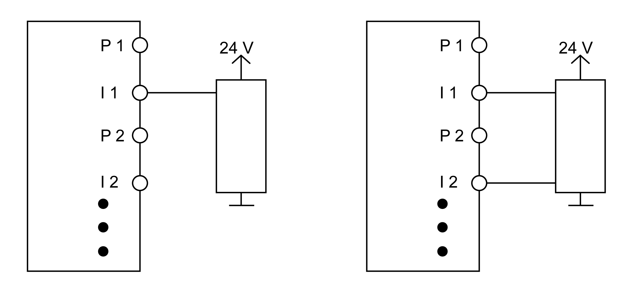
P Test (pulse) output
I Input
Electronic sensors (light curtain, laser scanners, inductive sensors) may also be connected to safety-related digital input modules.
Some electronic sensors feature OSSD (Output Signal Switching Device) outputs. These types of outputs include a pulse train similar to the test outputs of the Safety I/O module. However, these pulses are not exploitable by the module. For this reason, the input channels must be configured to PulseMode=none.
Further, gaps in the test of the connected OSSD outputs must be masked out with the switch-off filter of the module to help avoid false-positive safety-related requests. The configuration of a switch-off filter lengthens the safety-related response time.
| WARNING | |
|---|---|
When PulseMode=none, the module cannot detect wiring issues.
| WARNING | |
|---|---|
With single-channel wiring, the module corresponds to Category 3 according to EN ISO 13849. With two-channel wiring, the module corresponds to Category 4 according to EN ISO 13849. This only applies to the module and not to the wiring presented.
| WARNING | |
|---|---|
Make all necessary repairs in a timely manner if an error occurs because subsequent errors could create a hazardous situation.
| WARNING | |
|---|---|
Using the Same Test Outputs
When using the same test outputs for different inputs, the inputs must be isolated from one another. Otherwise, damage to the cables may cause errors that are not detected by the module.
The following graphic presents the connection with the same test (pulse) signals:
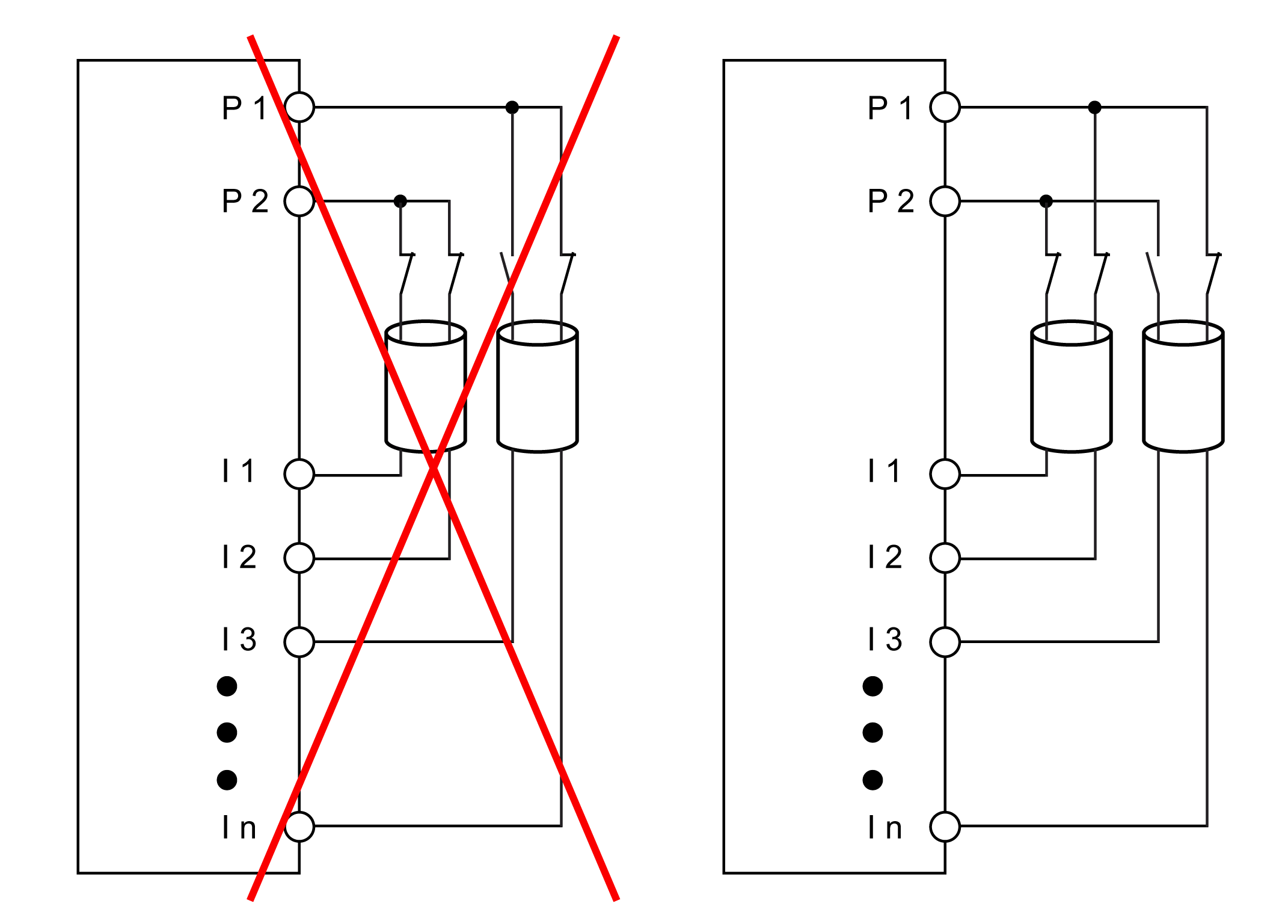
P Test (pulse) output
I Input
| WARNING | |
|---|---|