Connection Examples
Overview
The connection examples listed here only represent some of the possible wiring methods. However, the following must be taken into consideration regardless:
-
Two relay channels must be connected in series when used for a higher safety level (greater than or equal to category 2 or PL b according to ISO 13849 or SIL 1 according to IEC 62061).
-
The relay contacts must be protected with a fuse (Relay Output Characteristics).
| DANGER | |
|---|---|
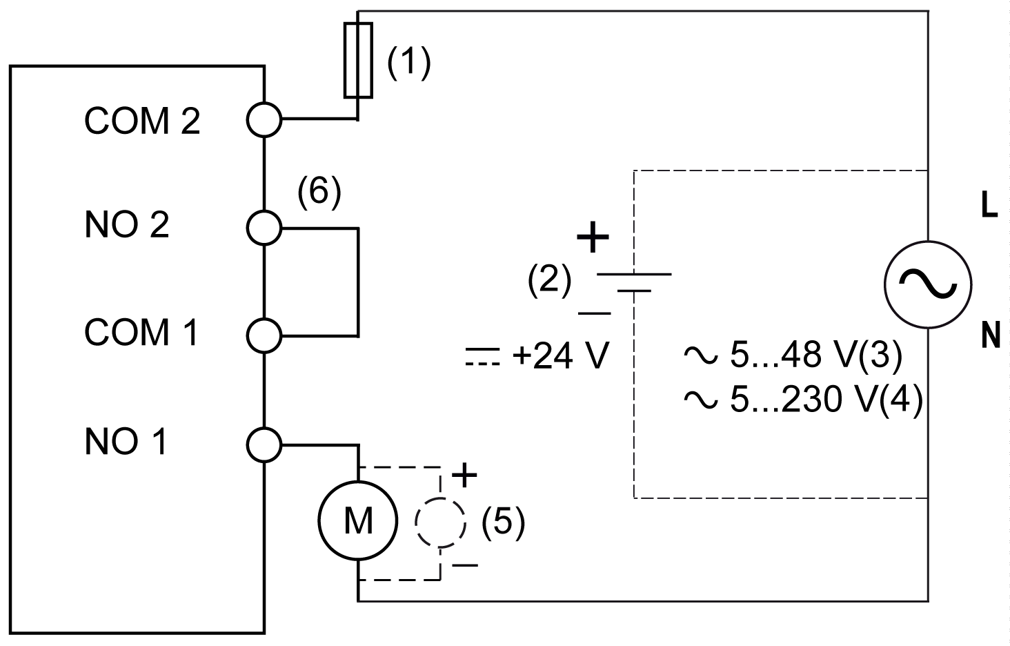
Connecting Safety-Oriented Actuators for Relay Outputs in Series

1 Fuse
2 External power supply 24 Vdc
3 External power supply 5...48 Vac (TM5SDM4DTRFS)
4 External power supply 5...230 Vac (TM5SDO2DTRFS)
5 Inductive load protection
6 External bridge NO 2 - COM 1
Inductive damage to relay types of outputs can result in welded contacts and loss of control. Each inductive load must be with a protection device such as a peak limiter, RC circuit or flyback diode. Capacitive loads are not supported by these relays.
| WARNING | |
|---|---|
For applications that correspond to SIL 3 or 4, the two normally closed contacts for the two relays must be wired in series. In this case, control of the two relays must be handled using signal SafeDigitalOutput0102.
Controlling the two relay contacts using the single signal SafeDigitalOutput01 and SafeDigitalOutput02 is invalid for applications corresponding to SIL 3 or 4 because certain operating states can cause the two normally closed contacts to weld together. Therefore, simultaneously using the signals SafeDigitalOutput0102 and SafeDigitalOutput01 or SafeDigitalOutput02 is restricted as such by the EcoStruxure Machine Expert - Safety software.
Using the signal SafeDigitalOutput0102 causes a switch-on sequence to be activated that switches on relay 2 with a 20 ms delay. This behavior is necessary to prevent welding of the two normally closed contacts in certain operating states.
| WARNING | |
|---|---|
A relay channel does not have error detection with regard to wiring issues. All errors resulting from damaged or incorrect wiring (including inappropriate loads) must be detected through supplementary measures or a connected device.
To help prevent possible error caused by short-circuits to other voltage levels, wiring that protects against short-circuits is needed for connecting the actuator.
Other errors that are not detected by the module (or not detected on time) may lead to unintended machine states and therefore must be uncovered using additional measures.
| WARNING | |
|---|---|
Make all necessary repairs in a timely manner if an error occurs because subsequent errors could create a hazardous situation.
| WARNING | |
|---|---|