Safety-Related Slice Description
Overview
The following figure shows the three components of a safety-related slice:
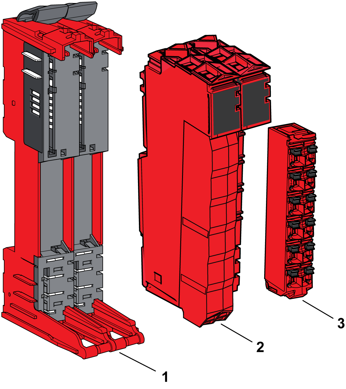
1 Safety-related bus base
2 Safety-related electronic module
3 Safety-related terminal block
| DANGER | |
|---|---|
The safety-related bus base and the safety-related terminal block for the safety-related electronic module, must be ordered separately. For the references see respective sections below.
When assembled the three components form an integral unit that resists vibration and electrostatic discharge.
| NOTICE | |
|---|---|
The compatibility table gives the possible associations between components of a slice.
Safety-Related Bus Base Description
The following figures shows the different parts of the safety-related bus base:
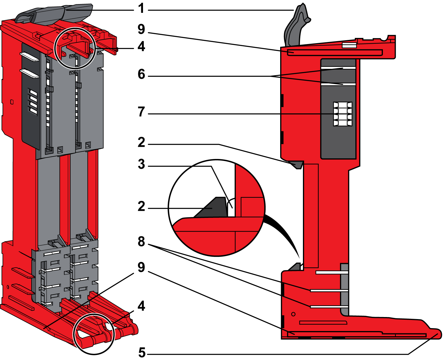
1 Locking lever
2 DIN rail locking mechanism
3 DIN rail contact
4 Guides for assembly of the safety-related electronic module
5 Rotation axle for safety-related terminal block
6 TM5 bus power contacts
7 TM5 bus data contacts
8 24 Vdc I/O power segment contacts
9 Interlocking guides
This table below presents the types of safety -related bus bases to be used in the safety-related slice:
|
Reference |
Safety-Related Bus Base Description |
Color |
|---|---|---|
|
TM5ACBM3FS |
Bus base 24 Vdc for safety-related modules, safety coded 24 Vdc I/O power segment pass-through |
Red |
|
TM5ACBM4FS |
Bus base 24 Vdc for safety-related modules, safety coded 24 Vdc I/O power segment left isolated |
Red |
Safety-Related Electronic Module Description
The following figure presents the different parts of the safety-related electronic modules:
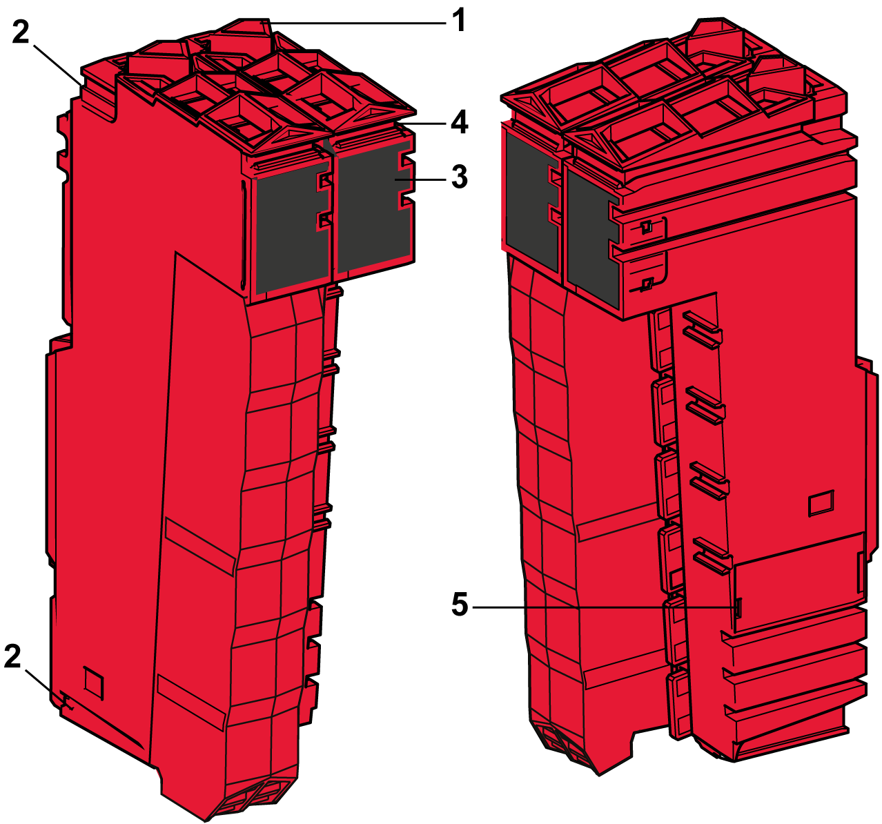
1 Locking lever
2 Guides for assembly
3 Display (LEDs)
4 Slot for labeling
5 Internal fuse exchangeable (depending on references)
This table presents the different types of safety-related electronic modules:
|
Reference |
Safety-Related Electronic Module Description |
Color |
Refer to |
|---|---|---|---|
|
TM5S•••FS |
Safety-related modules |
Red |
Safety-Related Terminal Block Description
The main features of the safety-related terminal block are:
-
Tool-free wiring with spring clamp push-in technology
-
Push-button wire release
-
Ability to label each terminal
-
Plain text labeling also possible
-
Test access for standard probes
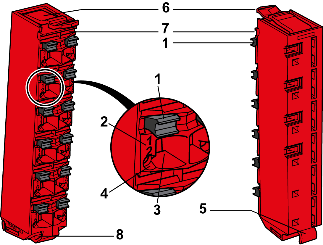
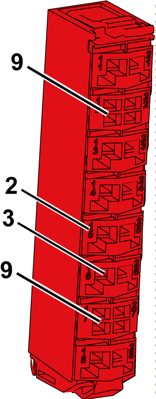
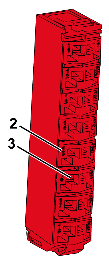
The following figures present the different parts of the safety-related terminal blocks:
|
TM5ACTB52FS |
TM5ACTB5EFS |
TM5ACTB5FFS |
|---|---|---|
|
|
|
|
1 Wire release push-button 2 Pin assignment 3 Spring clamp connector 4 Test access point 5 Hinge for the axle on the safety-related bus base 6 Latch for the safety-related electronic module 7 Front slot for labeling 8 Slot for cable tie 9 Access point to terminal temperature compensation |
||
This table presents the safety-related terminal blocks:
|
Reference |
Safety-Related Terminal Block Description |
Color |
|---|---|---|
|
TM5ACTB52FS |
24 Vdc / 230 Vac, 12-pin terminal block for safety-related modules and Safety Logic Controller, safety coded |
Red |
|
TM5ACTB5EFS |
24 Vdc, 16-pin terminal block for safety-related modules, safety coded, 2x PT1000 integrated for terminal temperature compensation |
Red |
|
TM5ACTB5FFS |
24 Vdc, 16-pin terminal block for safety-related modules, safety coded |
Red |