TM7SDI8DFS Presentation
Main Features
The following table describes the main features of the Safety Digital Input module TM7SDI8DFS:
|
Main features |
|
|---|---|
|
Number of inputs |
|
|
Input filter |
Configurable input filter, 0...500 ms |
|
Input circuit |
Sink |
|
Number of outputs |
|
|
Rated voltage |
24 Vdc |
| DANGER | |
|---|---|
Ordering Information
The following table presents the reference of the module:
|
Reference |
Description |
Color |
|---|---|---|
|
TM7SDI8DFS |
TM7 Safety Digital Input module |
red |
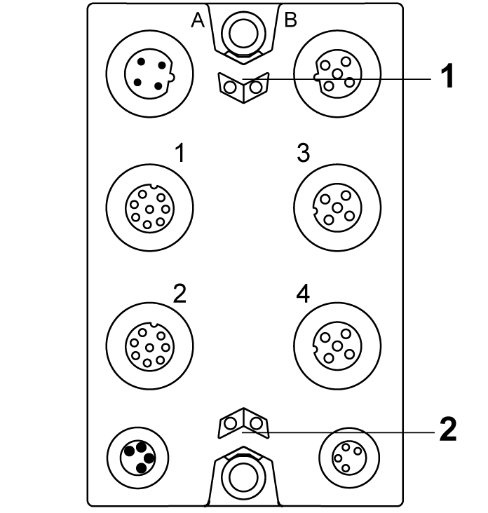
Status LED Indicators
This figure presents the status LED indicators:

1 Status LED indicators r and e: left green r, right red e
2 Status LED indicators S and E: left red S, right red E
The following tables describe the status LED indicators:
|
LED indicator |
Color |
Status |
Description |
|---|---|---|---|
|
r |
off |
Module supply not connected. |
|
|
green |
single flash |
reset mode |
|
|
double flash |
firmware update in progress |
||
|
flashing |
pre-operational state |
||
|
on |
RUN state |
||
|
e |
off |
No error detected or module supply not connected. |
|
|
red |
flashing |
boot loader mode |
|
|
triple flash |
firmware update in progress |
||
|
on |
error detected |
||
|
r+e |
steady red/single green flash |
invalid configuration |
|
|
LED indicator |
Color |
Status |
Description |
|---|---|---|---|
|
1 2 3 4 |
- |
status of the corresponding device |
|
|
off |
|
||
|
green |
on |
|
|
|
flashing |
|
||
|
red |
on |
|
|
|
flashing |
|
||
|
red / green |
flashing |
|
|
|
LED indicator |
Color |
Status |
Description |
|---|---|---|---|
|
SE |
off |
RUN state or 24 Vdc supply not present |
|
|
red |

|
boot phase or missing TM5 link or non-functioning processor (refer to hazard message below) |
|

|
pre-operational state |
||

|
communication channel is not OK |
||

|
firmware for this module is a non-certified pilot version
NOTE: If you observe this indication, you must immediately replace the module, or update its firmware with a certified version. In all cases, contact your Schneider Electric representative.
|
||

|
boot phase, inoperable firmware |
||
|
on |
Safety-related status is active. |
||
Whenever the SE LED indicator is illuminated continuously, this indicates that the module is inoperative. There is also a diagnostic available in the Safety Logic Controller to indicate this state. Replacement of the module must be made immediately.
| WARNING | |
|---|---|