System Planning
Overview
Specify the following when planning the Lexium™ MC12 multi carrier:
-
Identify a track geometry fitting to your machine layout and process. Also refer to Track Orientation.
-
Define a number of Lexium™ MC12 carriers to start with. Refer to System Limits.
-
Use the editor to configure the track, process stations, tools and products. Refer to Multicarrier Configuration Editor and EcoStruxure Machine Expert Twin.
-
Develop, verify and optimize your application and track geometry with the embedded emulation (). Refer to Multicarrier Configuration Editor and EcoStruxure Machine Expert Twin.
-
Verify that the application is within system limits. Refer to System Limits.
-
Specify associate equipment that is compatible with the strong magnetic fields of the equipment, such as capacitive sensors.
-
Derive the number of power supplies and place the power infeed interconnects at the track.
-
Dimension the braking resistors and define the feed points for the power and communication connections on the track. Refer to Dimensioning the Braking Resistor and the Interconnects.
-
Design the mounting plate of your track. Refer to Mounting Plate.
-
Include in your design an appropriate enclosure for the equipment and, according to your risk analysis, the appropriate safety-related devices and measures.
-
Design tools suitable for your application and install the tools on the Lexium™ MC12 carriers to transport your products within your track.
-
Include in your design and application a device (for example, a sensor) for identifying the carrier type and the type of tool mounted on the carrier to help prevent collisions.
System Limits
Track:
-
Maximum track length: 24 m (78.4 ft)
For longer systems, contact your local Schneider Electric service representative.
-
Maximum number of Lexium™ MC12 long stator motor segments per track: 82
-
Maximum number of Lexium™ MC12 carriers per track: 130
For a larger number of carriers, contact your local Schneider Electric service representative.
-
Maximum number of Lexium™ MC12 carriers per Lexium™ MC12 long stator motor segment straight: 6
-
Maximum number of Lexium™ MC12 carriers per Lexium™ MC12 long stator motor segment arc: 4
-
Total mass (carrier with tool and product): ≤ 3 kg (6.61 lb)
-
Maximum acceleration at 1 kg (2.2 lbs): 120 m/s² (394 ft/s²)
-
Maximum velocity: 4 m/s (13.1 ft/s)
Also refer to General Technical Data.
Power supply:
-
The power supplies feed the Lexium™ MC12 multi carrier track. For each power supply, you must place a Lexium™ MC connection module between the power supply output and the Lexium™ MC12 multi carrier track.
-
Up to a maximum of three power supply/Lexium™ MC connection module combinations can be used in parallel. If more than three power supplies are required, the track must be divided into power groups that are powered separately. For how to define power groups, refer to the different power interconnects (Lexium™ MC power interconnects / Power disconnector).
-
The universal power supply ABLU3A48200 is designed to handle the back feed voltage (braking voltage) from the Lexium™ MC12 multi carrier track during braking phase. Also refer to Connecting a Braking Resistor (CN2).
-
The Lexium™ MC12 multi carrier requires that the power supply must be dimensioned according to the number of segments, segment groups, carriers, load and other pertinent parameters.
The maximum number of 24 segments per power supply/Lexium™ MC connection module combination must not be exceeded.
Also refer to Power Supply.
Track Orientation
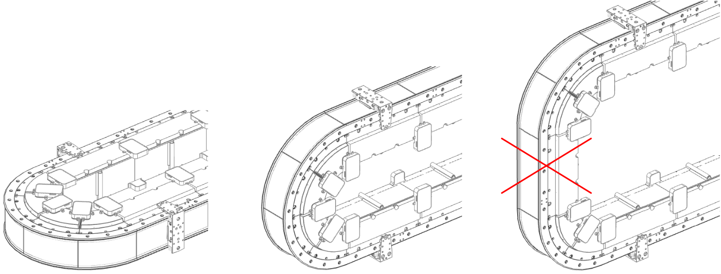
The track orientation can be horizontal or vertical but straight segments are only allowed in horizontal orientation, as illustrated:
| WARNING | |
|---|---|
Physical Coordinate System of the Track
The physical coordinate system of the track relates to the position of the Sercos infeed. The easiest solution is to put the Sercos infeed at the beginning of a straight segment (seen in clockwise direction).
Mounting Plate
The mounting plate must be prepared before installing the track. Refer to Mounting Plate.
Tools for the Carriers
You must install tools on the Lexium™ MC12 carriers to transport your products within your track.
Refer to Mounting the Tools on the Lexium™ MC12 carrier and Dimensions and Drilling Templates.
Dimensioning the Power Supply
The required power and the number of power supplies must be calculated depending on the desired performance characteristics of your track.
You can feed the DC bus at different points of the track. For example, feed at points where a high electrical load due to deceleration and acceleration is to be expected.
For dimensioning the power supply, contact your local Schneider Electric service representative.
Dimensioning the Braking Resistor and the Interconnects
The required braking resistor must be calculated depending on the desired braking capability and characteristics of your track. In addition, the number of Lexium™ MC power interconnects and Lexium™ MC communication interconnects and their optimized feed points on the track can be calculated.
Contact your local Schneider Electric service representative for these calculations.
Libraries and Example Project
EcoStruxure Machine Expert provides two libraries to program your Lexium™ MC12 multi carrier application:
-
EcoStruxure Machine Expert Multicarrier library
For controlling the Lexium™ MC12 multi carrier and moving the individual carriers.
For more information, refer to the Multicarrier library.
-
EcoStruxure Machine Expert MulticarrierStation library.
For controlling the handling of carriers within individual stations and between the stations.
For more information, refer to the MulticarrierStation library.
In addition, creating a new project in EcoStruxure Machine Expert using the example project will simplify your work (). For more information, refer to the Lexium™ MC multi carrier Example Guide.
Editor and
The editor is provided by Schneider Electric as a part of EcoStruxure Machine Expert.
It is used to configure a Lexium™ MC multi carrier from scratch or to modify an existing configuration. As a result, the editor adapts the device configuration in EcoStruxure Machine Expert, and generates or modifies code in the application.
You can use the editor to layout your track by adding and parameterizing the following components:
-
Straight and curved segments (pre-defined type, length, topological address, start position, end position)
-
Stations (name, waiting position, process position)
-
Carrier instances (number, carrier compounds)
-
Carrier compounds (name, description, properties)
-
Tools (name, description, properties)
-
Products (name, description, properties)
You can display the track and its components in simplified graphical representations.
For more information on the editor, refer to the Lexium™ MC multi carrier Configuration Guide.
The EcoStruxure Machine Expert installation includes the installation files of EcoStruxure Machine Expert Twin. EcoStruxure Machine Expert Twin can be used with the EcoStruxure Machine Expert license.
A viewer of is embedded in the editor. With this, you can display your configured track as a 3-D emulation and see your application running virtually (by usage of a controller but without real mechanics).
This helps you to analyze your application behavior and to optimize your track design.