Device Reactions - Drive
Overview
In the following table, the device reactions are sorted according to their priority (from High to Low).
|
Device reaction |
Diagnostic class |
Subclass |
Meaning |
Diagnostic example |
|---|---|---|---|---|
|
AD |
3 |
6 |
|
|
|
BD1 |
3 |
5 |
|
|
|
BD2 |
3 |
4 |
|
|
|
CD |
3 |
3 |
|
For this device reaction there is no diagnostic message defined by default. |
|
D |
2 |
2 |
Informing message to PacDrive LMC. The program can be used for controlled, synchronous shutdown. If the PacDrive LMC does not trigger a reaction in the drive a diagnostic message with the device reaction AD, BD1, BD2, or CD may occur. |
|
|
E |
1 |
1 |
Message |
The device reaction can be reconfigured by using the function FC_DiagConfigSet2 or FC_DiagConfigSubClassGroupSet. The priority of the configured device reaction must always be equal to or greater than the priority of the minimum device reaction. The minimum device reactions are indicated in the respective diagnostic message or in the overview table.
The above-mentioned device reactions are also triggered by the following events:
-
If ControllerEnable is set to FALSE and the AxisState is > 2, device reaction BD2 is triggered by default. The reaction can be changed by using the ControllerEnableStopMode parameter.
-
If TorqueEnable is set to FALSE and the AxisState is > 2, the device reaction AD is triggered.
In the event of reaction BD2, you can decide whether the defined shutdown profile starts with actual or reference values. In the PacDrive system, the term "actual" refers to real time, real world measured values. The term "reference" refers to values that are derived or otherwise calculated. By default, the profile is started with actual values:
|
Starting with actual values |
|
|
Starting with reference values |
|
Time Diagram for Reaction AD
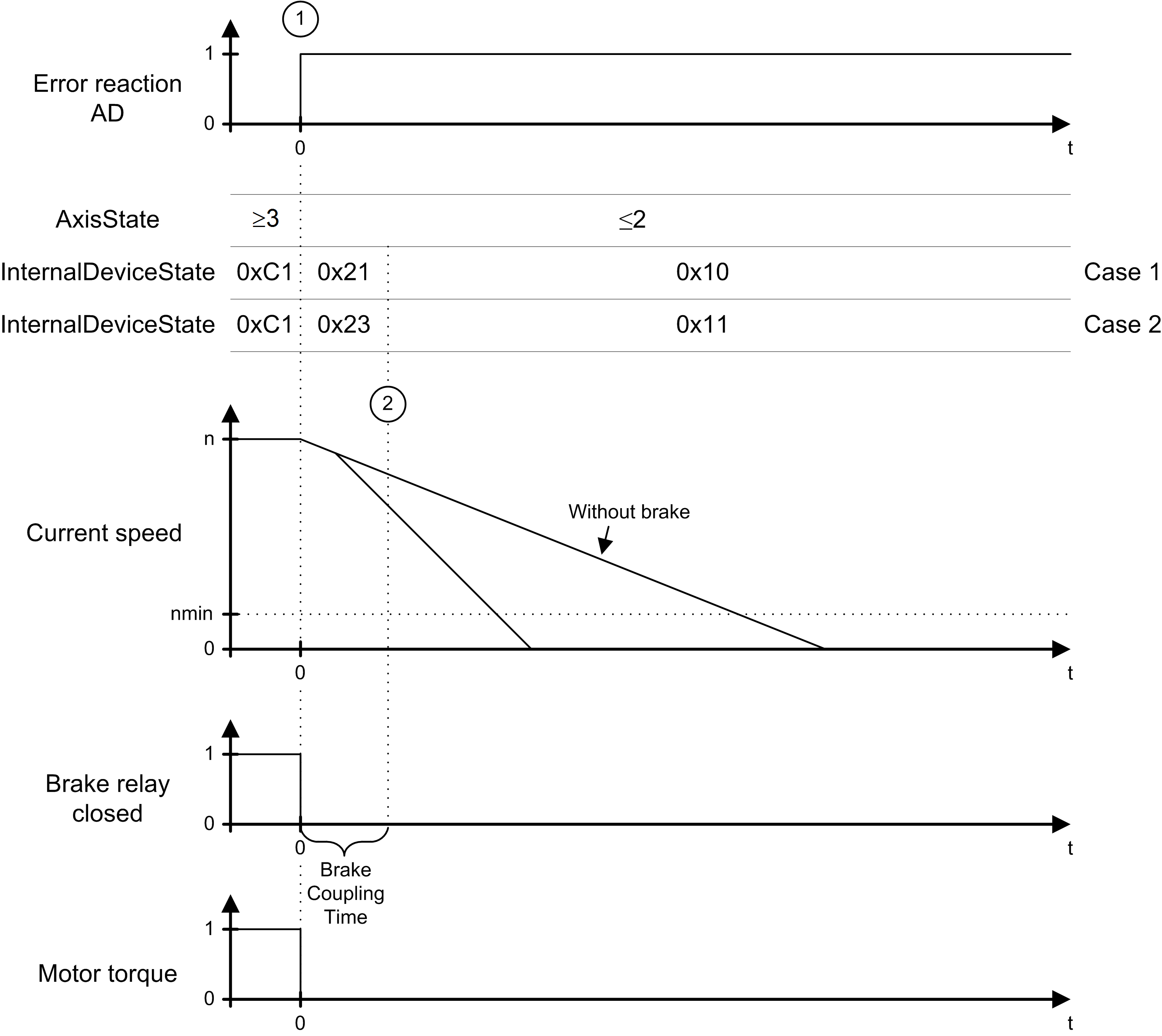
In the case of an error detected with the reaction AD (Drive) (1), the axis is switched torque-free immediately and the brake relay is released. The axis behavior depends on whether the motor is equipped with a holding brake or not.
Upon expiration of the BrakeCouplingTime, the axis is in the error state 0x10 or 0x11. To return from these states to a controlled state the diagnostic message has to be acknowledged and the axis has to come to a standstill.
The graphic shows the time diagram for reaction AD:

Time Diagram for Reactions BD1 / BD2
In case of a diagnostic message with reaction BD1 or BD2, two sequences can occur:
Ramping Down Within the Maximum Ramp-Down time
|
If... |
Then... |
|---|---|
|
An error is detected with reaction BD1 (1). |
The axis ramps down at maximum current (MaxDrivePeakCurrent). |
|
An error detected with reaction BD2 (1). |
The axis ramps down according to the parameter ControllerStopDec and ControllerStopJerk. |
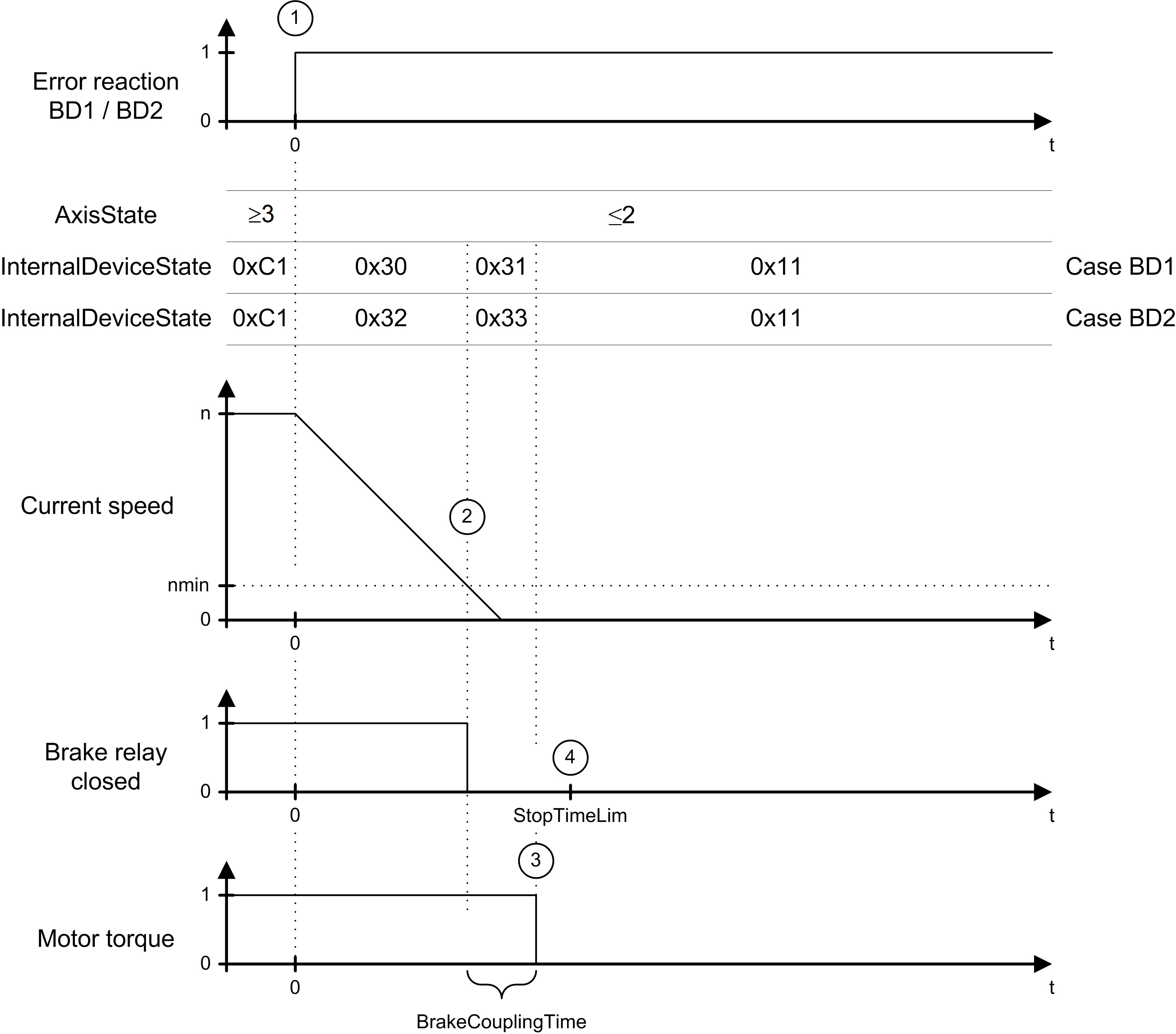
As soon as the actual speed becomes lower than the speed threshold (actual speed < nmin) (2), the brake relay is switched to couple the brake.
The axis comes to a standstill before expiration of the maximum ramp-down time (parameter StopTimeLim) (4). After expiration of the brake coupling time (parameter BrakeCouplingTime) (3), the motor is switched to a torque-free state.
The graphic shows the time diagram for reaction BD1 / BD2 (ramping down within the max. ramp down time):

Maximum Ramp-Down time Exceeded
|
If... |
Then... |
|---|---|
|
An error is detected with reaction BD1 (1). |
The axis ramps down at maximum current (MaxDrivePeakCurrent). |
|
An error is detected with reaction BD2 (1). |
The axis ramps down according to the parameter ControllerStopDec and ControllerStopJerk. |
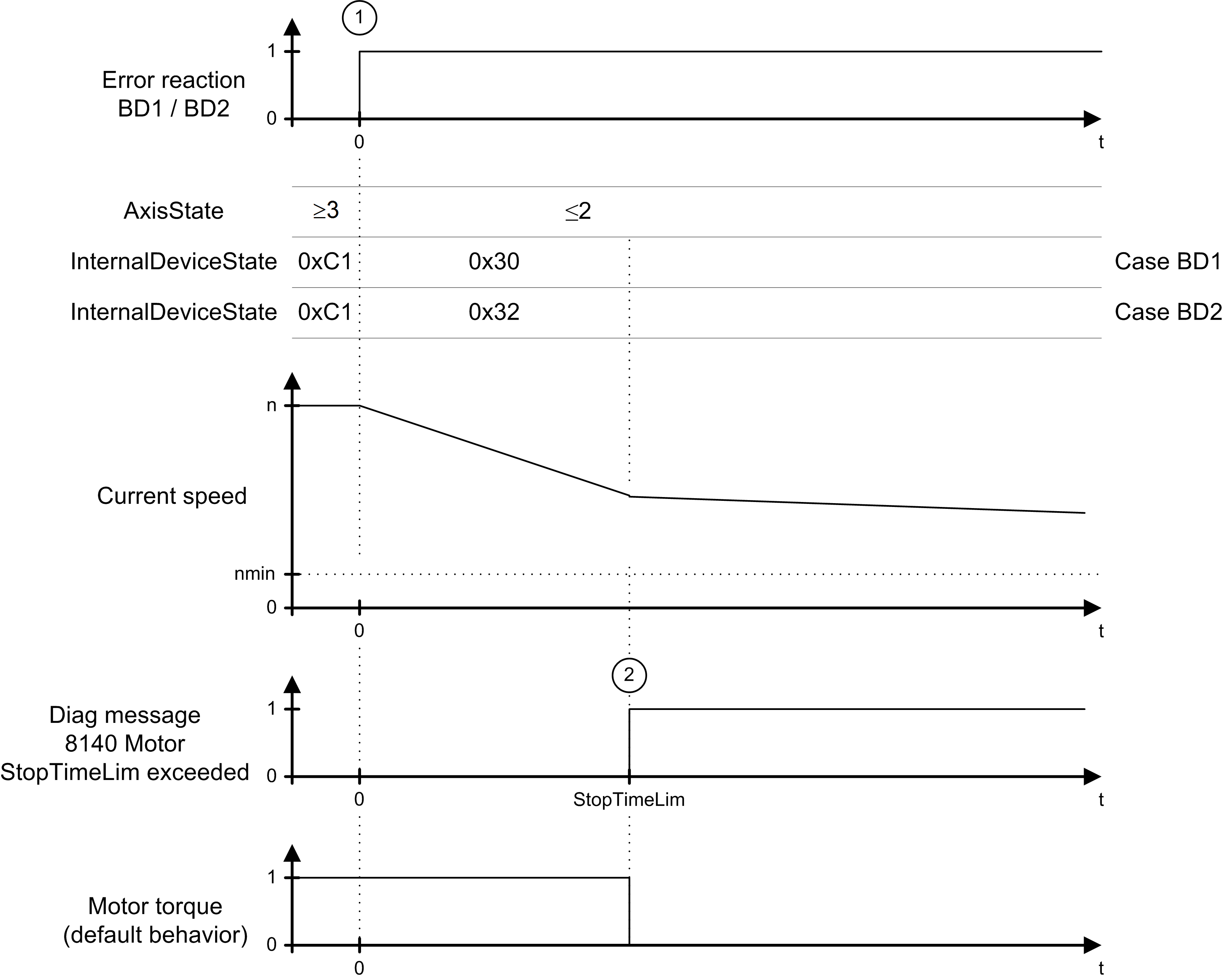
The axis does not come to a standstill before expiration of the maximum ramp-down time (parameter StopTimeLim) (2) (actual speed < nmin). Therefore, error message 8140 Motor ramp-down time exceeded is triggered.
The graphic shows the time diagram for reaction BD1 / BD2 (maximum ramp down time exceeded):
