Tab 'Modbus Slave Channel'
Object: Modbus Slave Serial, Modbus Slave TCP
You use this tab to define slave channels.
Each channel represents a single Modbus request.
Dialog 'ModbusChannel'
|
Name |
A string that contains the name of the channel |
|
Access type |
|
|
Trigger |
|
|
Cycle time (ms) |
For Trigger = CYCLIC: Request interval Note: The request interval should be the same as or a multiple of the cycle time of the application. |
|
Comment |
Description of the channel |
|
Offset |
Start address where reading should start (value range 0-65535) |
|
Length |
Number of registers to be read (for word access) or number of discrete inputs to be read (for bit access) |
|
Error handling |
Defines what should happen to the data in case of a communication error
|
|
Offset |
Number of the register to be written to (value range 0-65535) |
|
Length |
Number of registers to be written to (= Words) The value range of the parameter depends on function code. |
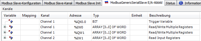
Example
In the following example, the first line defines a combined read/write operation (function code 23). It reads a word from the holding register with offset 16#0001 and writes two words to the register with offset 16#0003. The operation is performed as soon as the trigger variable defined in the tab I/O Mapping shows a rising edge.

See also