Coding the TM5 System
Introduction
To help reduce the likelihood of mismatches during mounting and maintenance operations, the association between the terminal blocks and the electronic modules can be coded.
The following image illustrates a coding of the electronic module and of the terminal block:
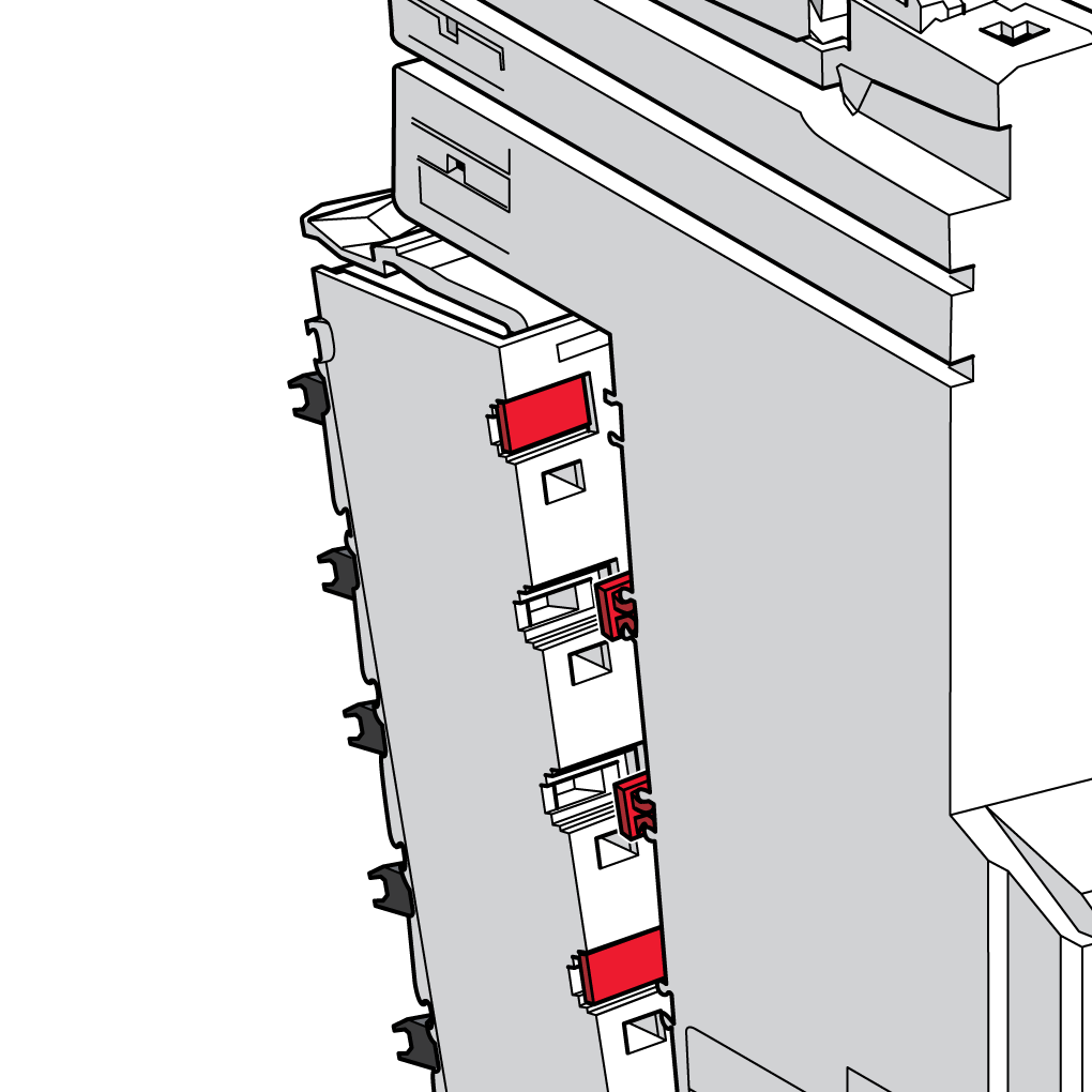
The label tabs and labeling tool accessories are required to code the terminal block and the electronic module.
Creating a Coding Scheme
There are many coding schemes you can use for the TM5 System. Here are some strategies that you can use:
-
Code adjacent modules differently.
-
Code each type of slice (input, output, digital, analog, 24 Vdc, 120 Vac, 240 Vac...) with a different pattern.
-
Be sure your coding scheme is unique.
The following table shows you some unique combinations to code your TM5 System:
|
1 |
2 |
3 |
4 |
5 |
6 |
||||||
|---|---|---|---|---|---|---|---|---|---|---|---|
|
A |
B |
A |
B |
A |
B |
A |
B |
A |
B |
A |
B |

|

|

|

|

|

|
||||||
|
A Slots on the terminal block B Slots on the electronic module
|
|||||||||||
How to Install the Label Tabs for Coding
The following table describes how to code the terminal block and the electronic module:
|
Step |
Action |
|
|---|---|---|
|
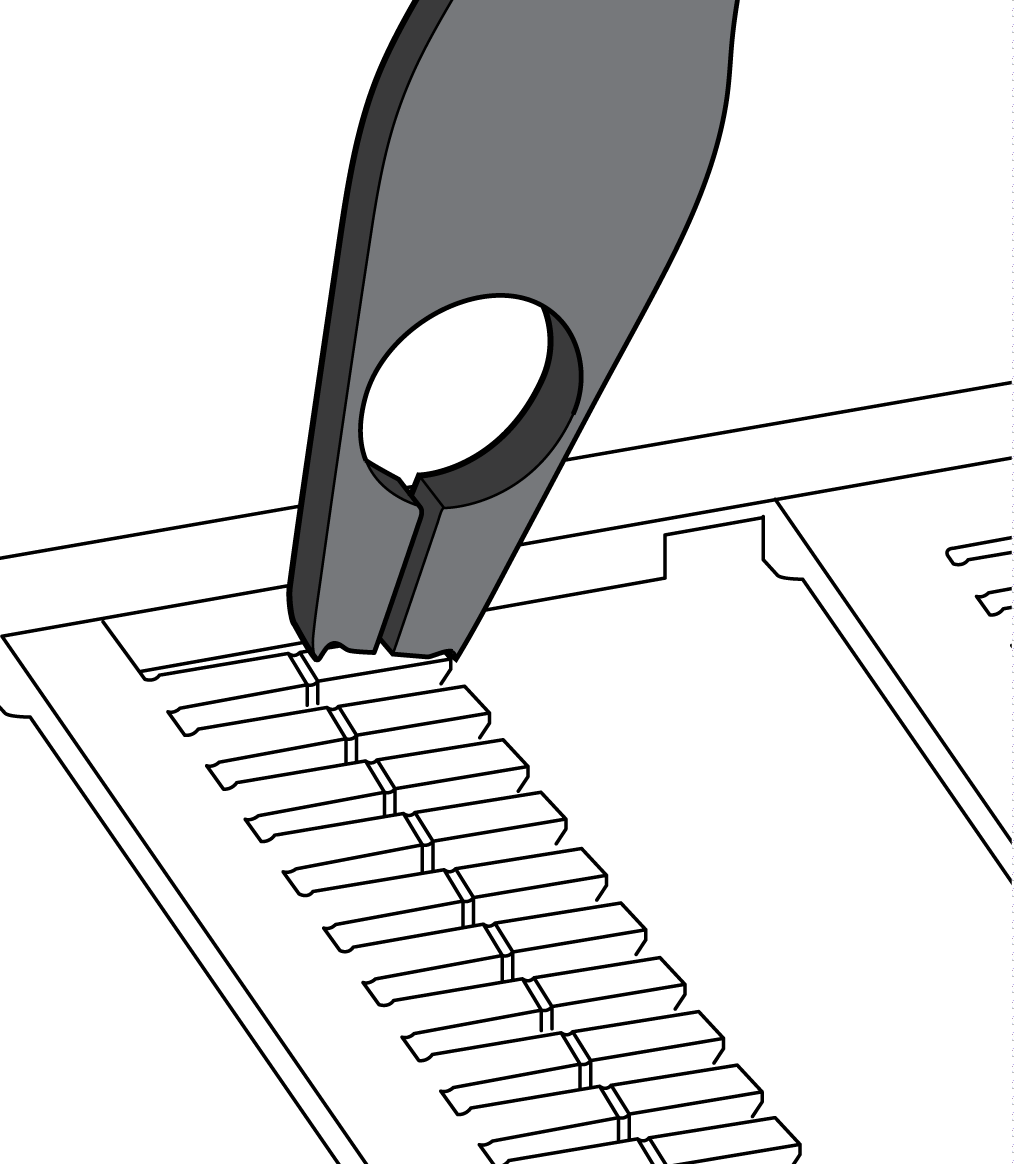
1 |
Grip the desired label tab with the single-width cutters of the labeling tool. |
|
|
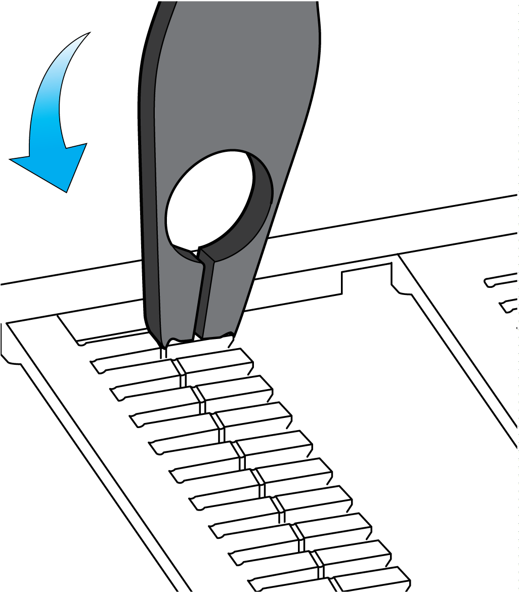
2 |
Press with the labeling tool to separate the label. |
|
|
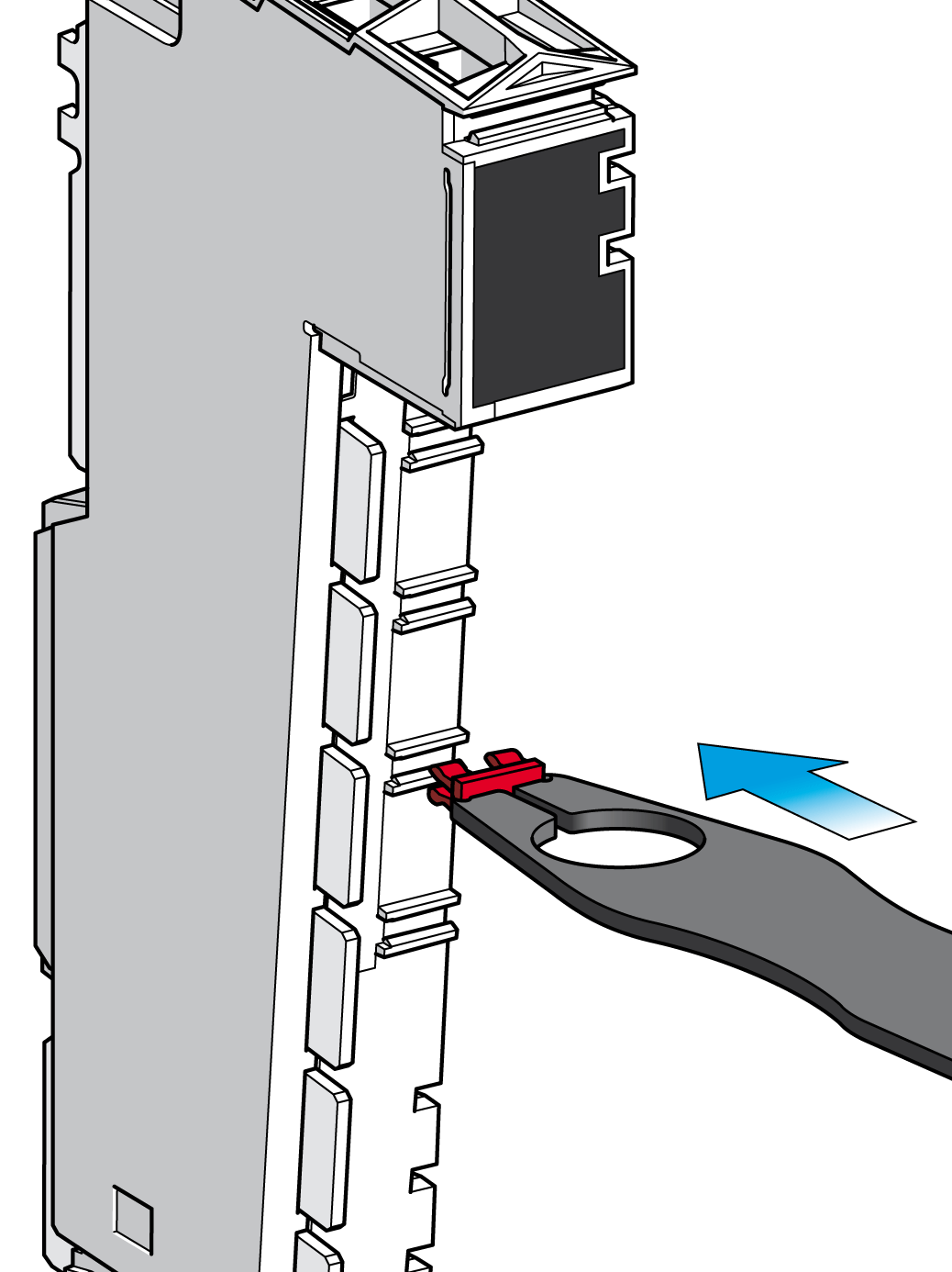
3 |
Center the label tab over the slot on the electronic module. |
|
|
4 |
Hold the labeling tool at a 90° angle to the electronic module and press to insert the label's feet into the slot.
NOTE: Repeat step 1 and 2 to remove a label tab with the single-width cutter of the labeling tool.
|
|
|
5 |
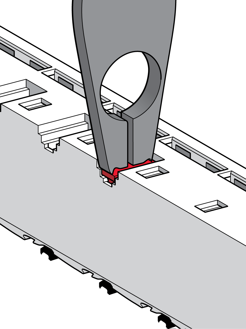
Set the label tab in the slot on the back of the terminal block as shown. |
|
|
6 |
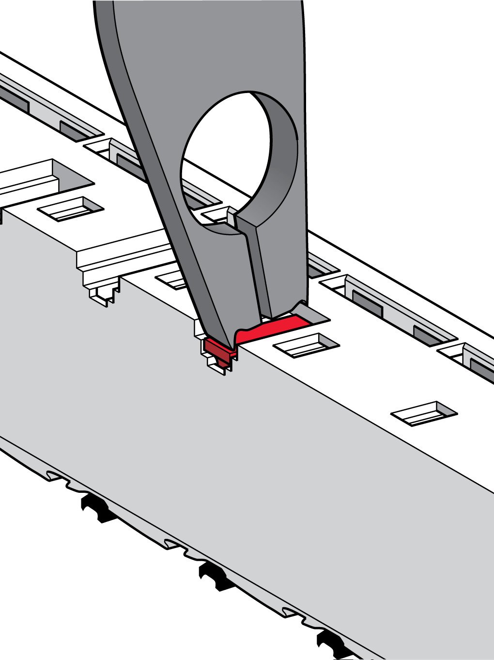
Use the labeling tool to push the left feet of the label into the slot. |
|
|
7 |
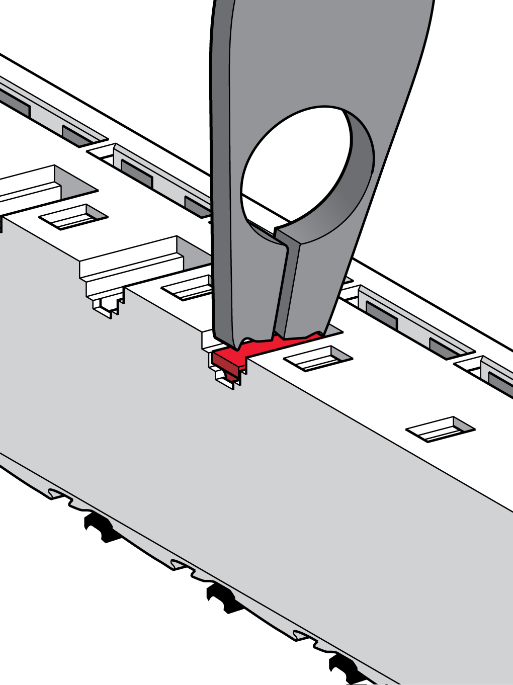
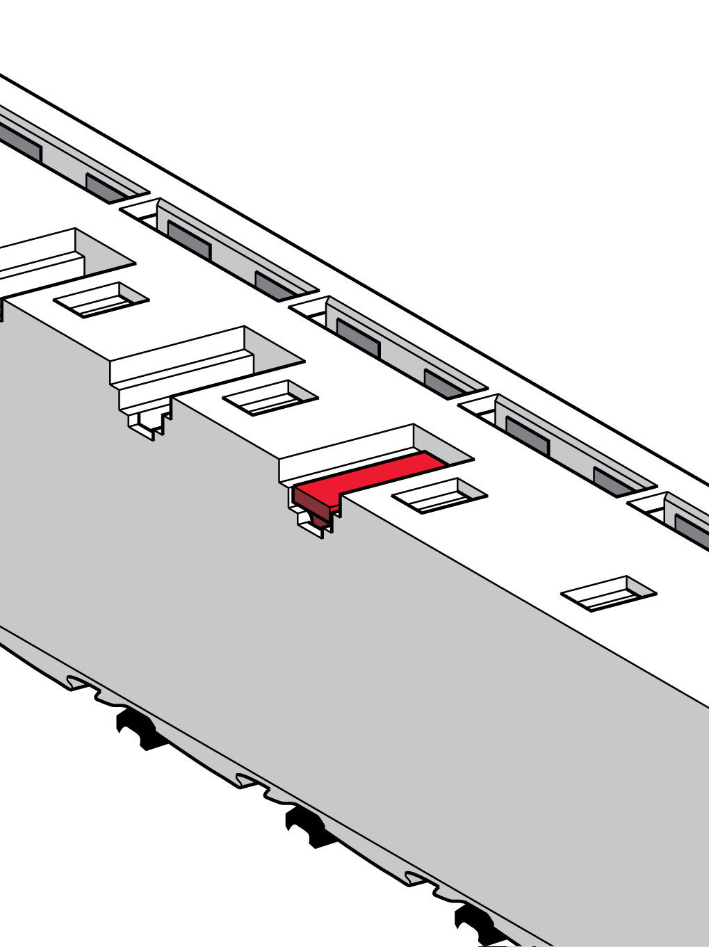
With the labeling tool, press the right feet of the label into the slot. Result: Inserted label for terminal coding. |
|
 represents an
  represents an electronic module slot without a label tab.
 represents a
  represents a terminal block slot without a label tab.