Replacing the Deflection Pulleys
Replacing the deflection pulleys can cause unintended movements.
|
|
|
UNINTENDED MOVEMENTS DUE TO DISMOUNTING |
|
Secure the moving parts of the axis mounted in a vertical or tilted position against unintended movements. |
|
Failure to follow these instructions can result in death, serious injury, or equipment damage. |
You need the following tools to replace the deflection pulleys:
oSet of hex keys
oTorque wrench with a set of hexagon sockets
NOTE: Do not use ball head hex keys. Excessive torque may cause, the ball head to tear off. A torn off ball head is difficult to remove from the screw.
For suitable parts, refer to Replacement Equipment and Accessories.
Perform the following procedures to replace the deflection pulleys:
oPreparing the replacement of the deflections pulleys
oReplacing the deflection pulleys
Preparing the Replacement of the Deflection Pulleys
|
Step |
Action |
|---|---|
|
1 |
NOTE: When replacing the deflection pulleys only, you do not have to remove the shaft extension. |
|
2 |
Remove the motor and/or gearbox as described in Replacing the Motor and/or Gearbox. |
|
3 |
Clean all parts. |
|
4 |
Inspect all parts for damage. |
NOTE: Polluted or damaged parts may cause run-out which has an adverse effect on the service life of the axis.
|
NOTICE |
|
UNINTENDED EQUIPMENT OPERATION |
|
oReplace any damaged parts immediately. oClean all parts before assembly and use. |
|
Failure to follow these instructions can result in equipment damage. |
Replacing the Deflection Pulleys
|
Step |
Action |
|---|---|
|
1 |
Remove the four outer screws (1) on the motor adapter plate (2). 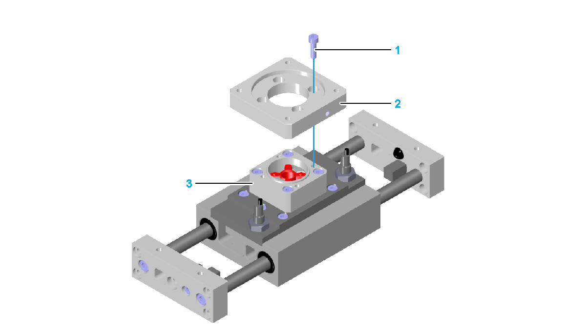
|
|
2 |
Remove the motor adapter plate (2) from the coupling housing (3). |
|
3 |
Remove the four outer screws (4) on the axis body adapter plate (5). 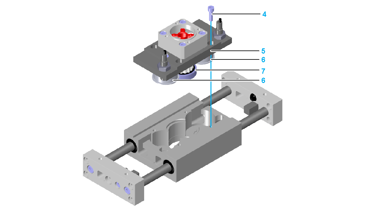
|
|
4 |
Remove the axis body adapter plate complete with the toothed belt pulley (7), the two deflection pulleys (6) and the coupling housing as a unit. |
|
5 |
Remove the two screws (8) in the middle at the axis body adapter plate. NOTE: Secure the deflection pulleys and the toothed belt pulley to keep it from falling. 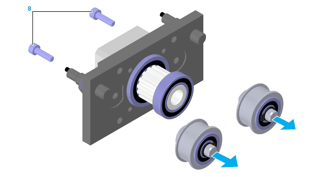
|
|
6 |
Remove the deflection pulleys. |
|
7 |
Insert the new deflection pulleys carefully into the axis body adapter plate. |
|
8 |
Mount the deflection pulleys to the axis body adapter plate with the two screws in the middle. Use a low tightening torque to allow the pulleys to move easily. |
|
9 |
|
|
10 |
If applicable, mount the motor and/or gearbox. |
|
Step |
Action |
|---|---|
|
1 |
Remove the four outer screws (1) and the two screws in the middle (2) at the axis body adapter plate (5). 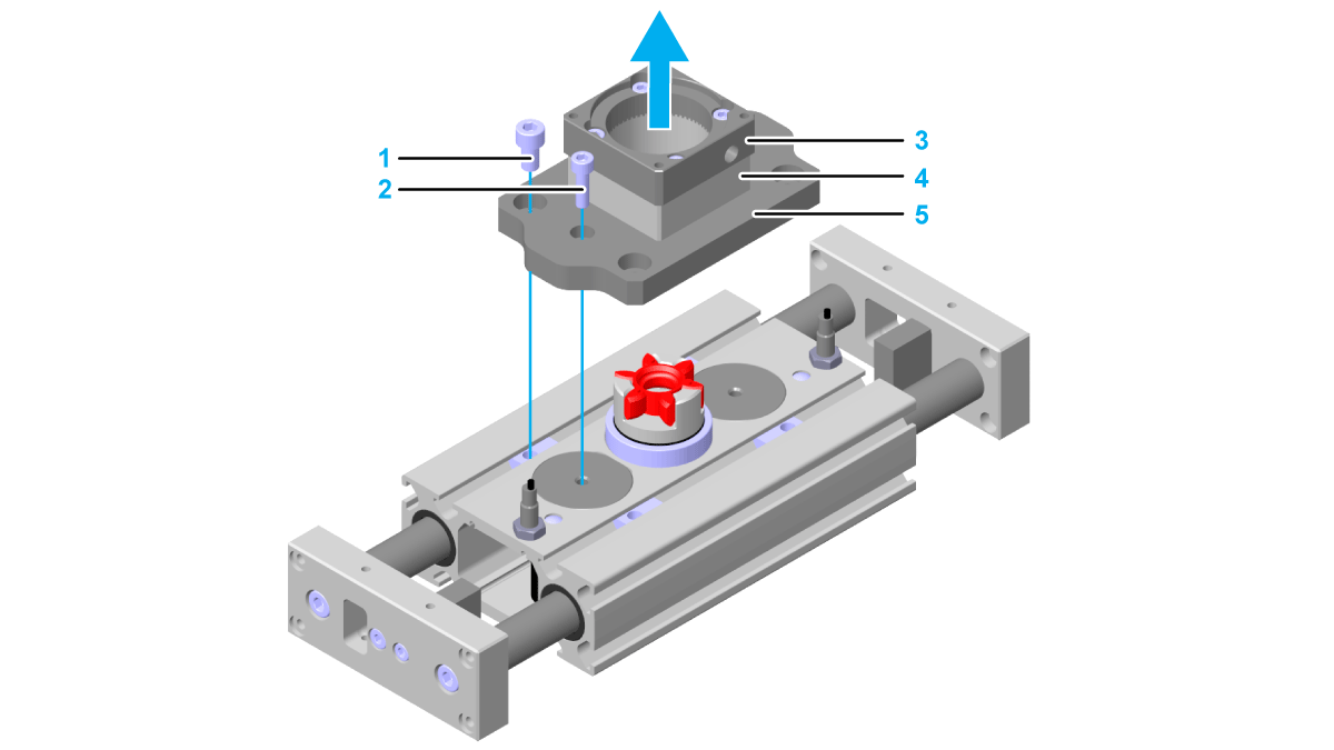
|
|
2 |
Remove the axis body adapter plate with the coupling housing (4) and the motor adapter plate (3) as a unit. |
|
3 |
Remove the toothed belt pulley (6) and the two deflection pulleys (7). 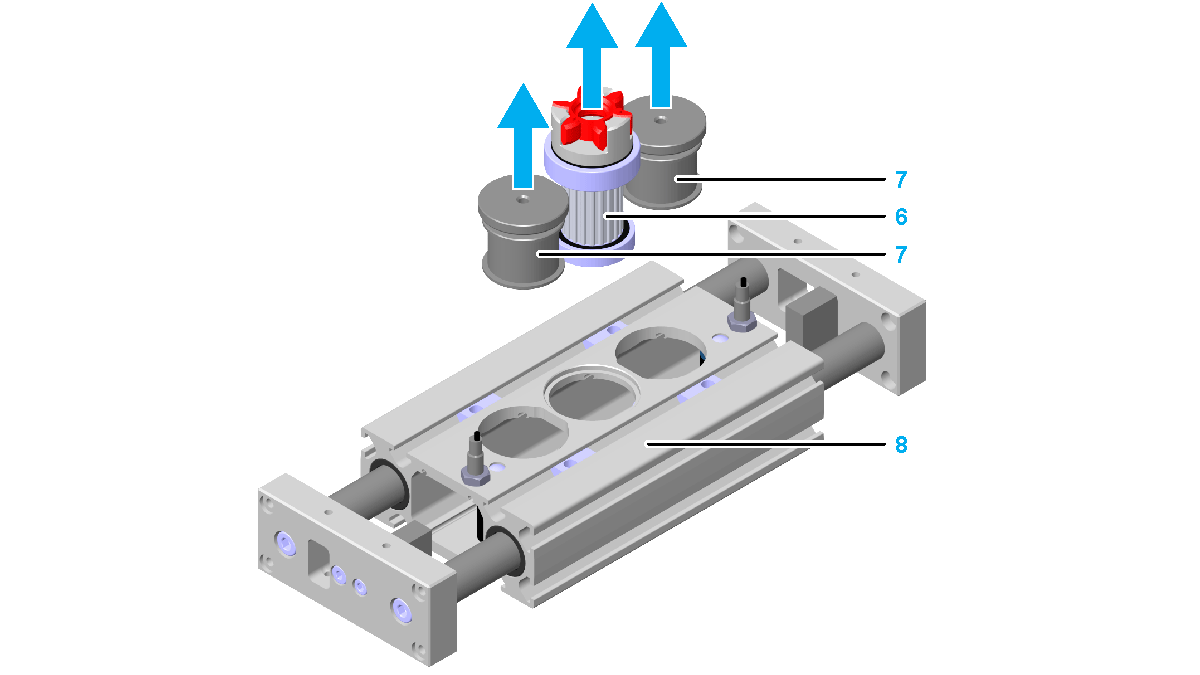
|
|
4 |
Clean all bearing seats in the axis body (8) and, if necessary, clean the axis body. |
|
5 |
Insert the two new deflection pulleys into the axis body. Verify that the deflection pulleys and the axis body are plane. 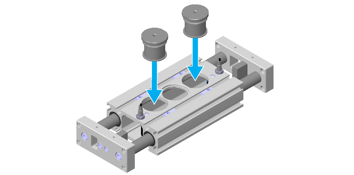
|
|
6 |
|
|
7 |
If applicable, mount the motor or gearbox. |