Mounting the Payload to the Tilting Modules
Mounting the Gripper to the Tilting Module B
|
Step |
Action |
|---|---|
|
1 |
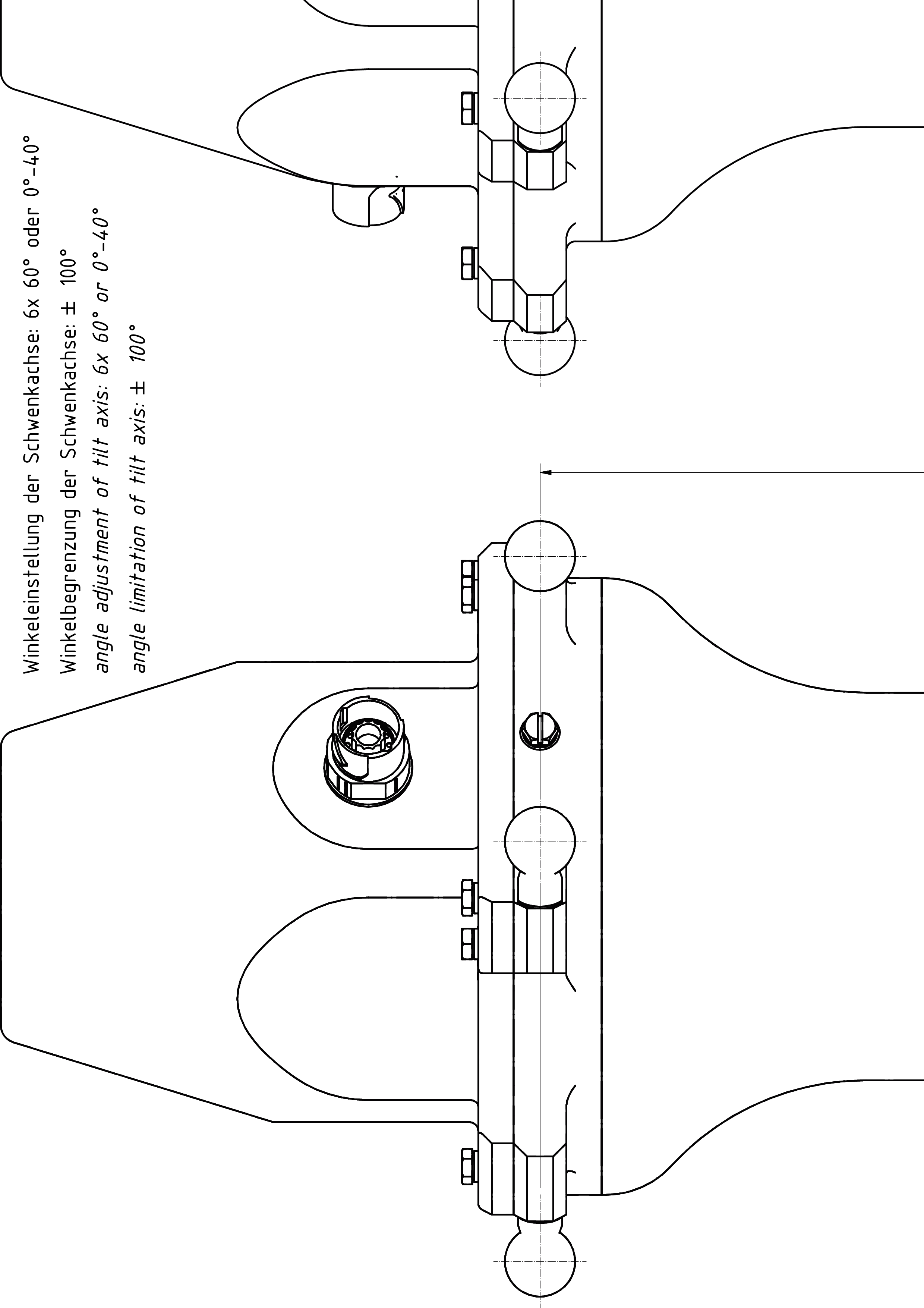
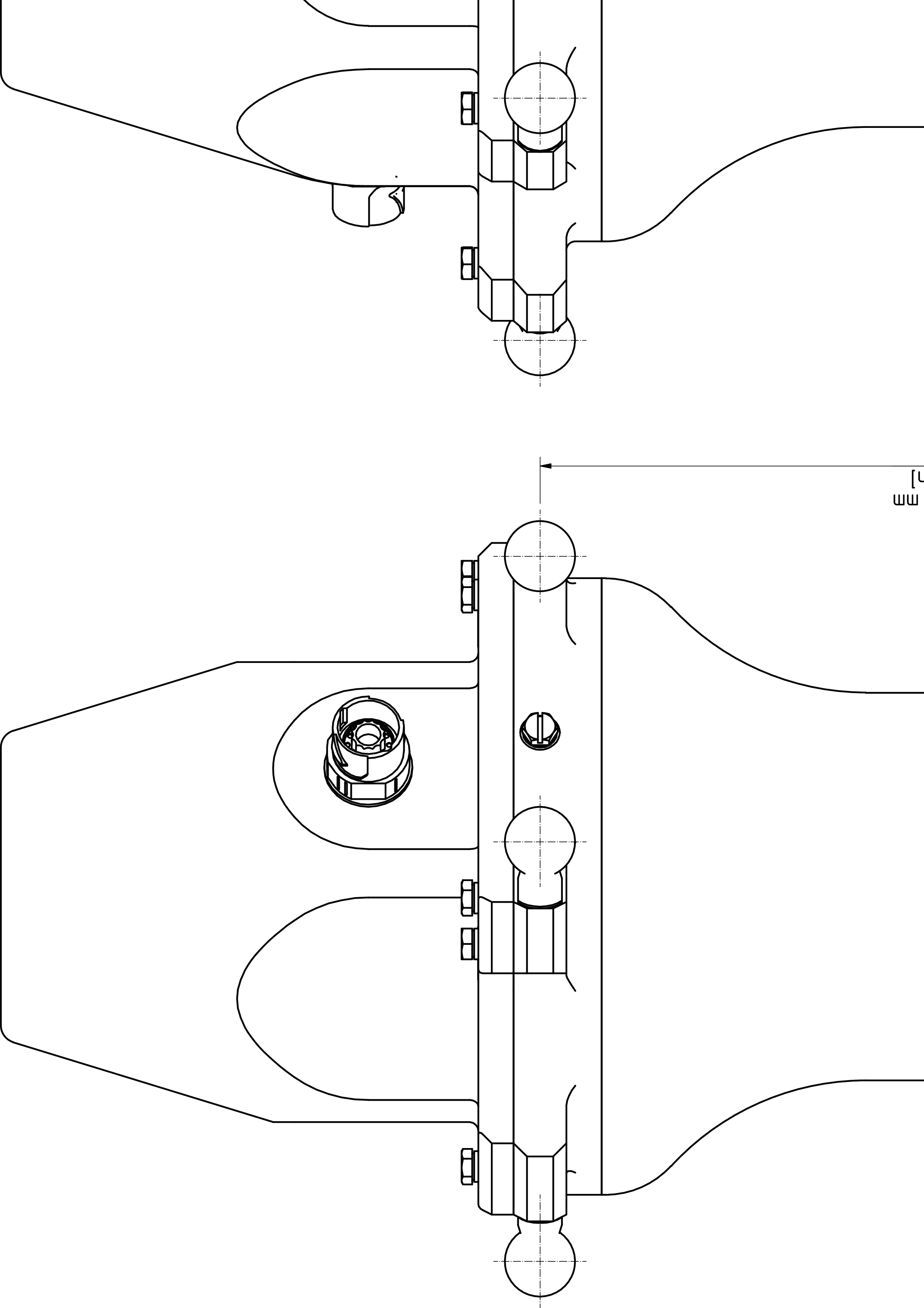
Fasten the gripper to the mounting points at the flange (1):
For further information, refer to Flange Dimensions for the Tilting Module B. 
|
|
2 |
Calibrate the Tilting Module B if this has not been done before mounting the gripper. For further information, refer to Calibrating the Tilting Module.
NOTE:
|
Mounting the Gripper to the Tilting Module HT-B-HD
|
Step |
Action |
|---|---|
|
1 |
Fasten the gripper to the mounting points at the flange (1):
For further information, refer to Flange Dimensions for the Tilting Module HT-B-HD. 
|
|
2 |
Calibrate the Tilting Module HT-B-HD if this has not been done before mounting the gripper. For further information, refer to Calibrating the Tilting Module.
NOTE:
|