Installation of the Safety Module eSM
General
| DANGER | |
|---|---|
| DANGER | |
|---|---|
The safety-related function STO (Safe Torque Off) does not remove power from the DC bus. The safety-related function STO only removes power to the motor. The DC bus voltage and the mains voltage to the drive are still present.
| DANGER | |
|---|---|
Conductive foreign objects, dust or liquids may cause safety-related functions to become inoperative.
| WARNING | |
|---|---|
Signal interference can cause unexpected responses of the drive system and of other equipment in the vicinity of the drive system.
| WARNING | |
|---|---|
Mechanical Installation
Electrostatic discharge (ESD) may permanently damage the module either immediately or over time.
| NOTICE | |
|---|---|
Commission the drive before installing the safety module eSM if your machine/process permits to do so.
Install the module according to the instructions in the user guide of the drive (Related Documents).
Electrical Installation - Interface
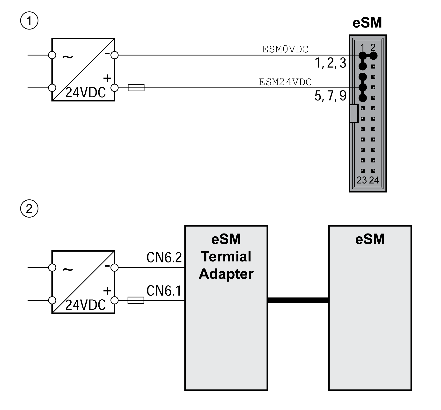
The safety module eSM is connected by means of a 24-pin connector.
Refer to Accessories and Spare Parts for information on suitable cables and terminal adapters for the safety module.
Electrical Installation - Cable Specifications
|
Characteristic |
Unit |
Value |
|---|---|---|
|
Shield |
- |
Not required |
|
Shield connected at one end |
- |
Not required |
|
Protected cable installation as per ISO 13849-2 |
- |
Required |
|
Minimum conductor cross section |
mm2 (AWG) |
0.34 (22) |
|
Maximum cable length between safety module eSM and eSM terminal adapter |
m (ft) |
3 (9.84) |
|
NOTE: Do not use ribbon cables.
|
||
-
Observe the EMC requirements specified in the user guide of the drive (Related Documents).
-
Use pre-assembled cables.
-
Verify that wiring, cables and connected interfaces meet the PELV requirements.
Electrical Installation - STO Inputs of the Drive
The safety-related function STO can be triggered directly via two inputs of the drive (refer to the user guide of the drive (Related Documents)). If you do not want to trigger the safety-related function STO via a signal at the inputs STO_A and STO_B of the safety module eSM, connect the inputs STO_A and STO_B to +24VDC.
Electrical Installation - Connecting the Inputs and Outputs
Pin assignment of the eSM connector:
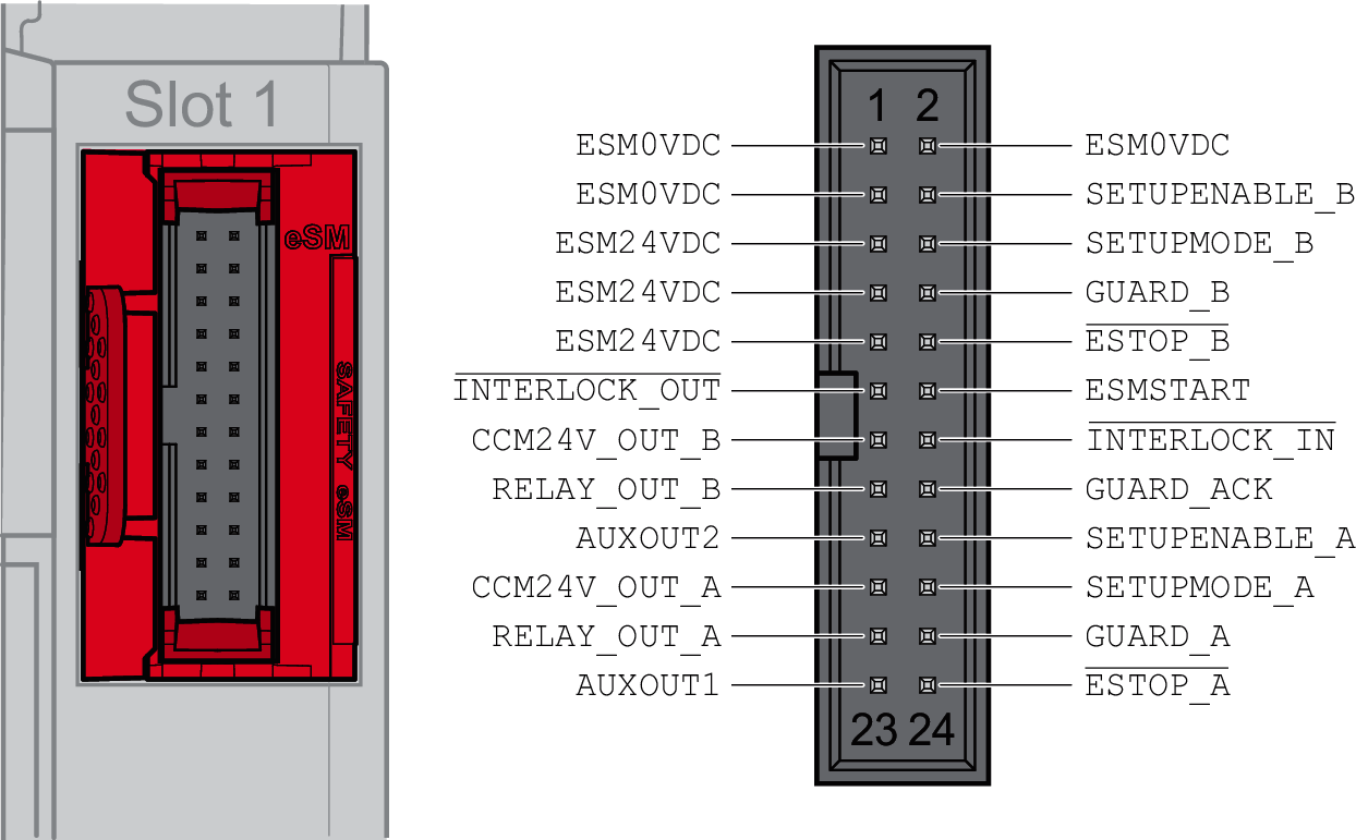
|
Pin |
Signal |
Active level |
Explanation |
Wire color(1) |
I/O |
|---|---|---|---|---|---|
|
1 |
ESM0VDC |
- |
Reference potential supply safety module eSM |
White |
- |
|
2 |
ESM0VDC |
- |
Reference potential supply safety module eSM |
Brown |
- |
|
3 |
ESM0VDC |
- |
Reference potential supply safety module eSM |
Green |
- |
|
4 |
SETUPENABLE_B |
1 |
Enabling device, channel B |
Yellow |
I |
|
5 |
ESM24VDC |
- |
Supply safety module eSM |
Gray |
- |
|
6 |
SETUPMODE_B |
1 |
Activation of the machine operating mode Setup Mode, channel B |
Pink |
I |
|
7 |
ESM24VDC |
- |
Supply safety module eSM |
Blue |
- |
|
8 |
GUARD_B |
1 |
Guard door, channel B |
Red |
I |
|
9 |
ESM24VDC |
- |
Supply safety module eSM |
Black |
- |
|
10 |
ESTOP_B |
0 |
Emergency Stop request, channel B |
Violet |
I |
|
11 |
INTERLOCK_OUT |
0 |
Guard locking device of guard door |
Pink, gray |
O |
|
12 |
ESMSTART |
1 |
Start/restart signal |
Blue, red |
I |
|
13 |
CCM24V_OUT_B |
1 |
Supply for input device/sensor, channel B |
White, green |
O |
|
14 |
INTERLOCK_IN |
0 |
Release input for interlock device of guard door |
Brown, green |
I |
|
15 |
RELAY_OUT_B |
1 |
Relay, channel B (for switching of external loads) |
White, yellow |
O |
|
16 |
GUARD_ACK |
1 |
Acknowledge/reset pushbutton |
Yellow, brown |
I |
|
17 |
AUXOUT2 |
1 |
Non-safety-related status output 2 |
White, gray |
O |
|
18 |
SETUPENABLE_A |
1 |
Enabling device, channel A |
Gray, brown |
I |
|
19 |
CCM24V_OUT_A |
1 |
Supply for input device/sensor, channel A |
White, pink |
O |
|
20 |
SETUPMODE_A |
1 |
Activation of machine operating mode Setup Mode, channel A |
Pink, brown |
I |
|
21 |
RELAY_OUT_A |
1 |
Relay, channel A (for switching of external loads) |
White, blue |
O |
|
22 |
GUARD_A |
1 |
Guard door, channel A |
Brown, blue |
I |
|
23 |
AUXOUT1 |
1 |
Non-safety-related status output 1 |
White, red |
O |
|
24 |
ESTOP_A |
0 |
Emergency Stop request, channel A |
Brown, red |
I |
(1) Colors of wires of cable VW3M8801R30, refer to Accessories and Spare Parts.