Lexium™ MC connection module
Overview
-
The power supplies feed the Lexium™ MC12 multi carrier track. For each power supply, you must place a Lexium™ MC connection module between the power supply output and the Lexium™ MC12 multi carrier track.
-
Up to a maximum of three power supply/Lexium™ MC connection module combinations can be used in parallel. If more than three power supplies are required, the track must be divided into power groups that are powered separately. For how to define power groups, refer to the different power interconnects (Lexium™ MC power interconnects / Power disconnector).
-
The Lexium™ MC connection module supplies the Lexium™ MC12 multi carrier track with power (DC bus).
The Lexium™ MC connection module limits the DC bus voltage to <60 Vdc, conforming to Functional Safety rules. Refer to Scope of Operation (Designated Safety Function).
Also refer to:
|
Element |
Description |
|---|---|
|
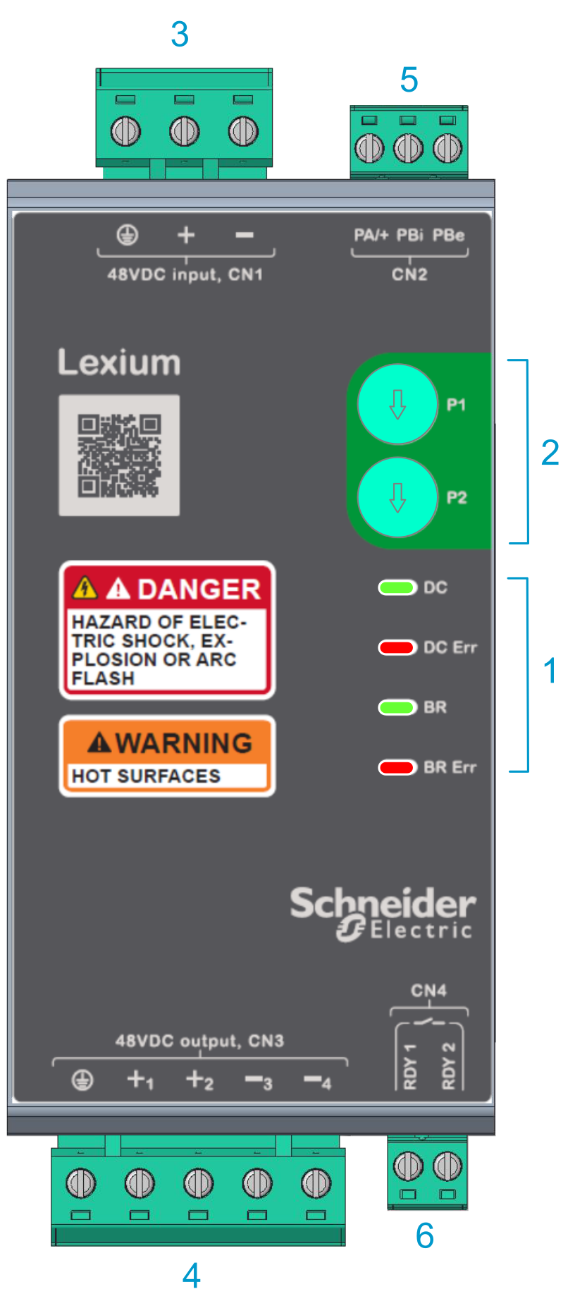
1 |
Status LEDs (DC, DC Err, BR, BR Err). Refer to Status LEDs. |
|
2 |
Rotary switches (P1, P2) for the braking resistors and voltage level. Refer to Switches. |
|
3 |
CN1: 48 Vdc input from power supply (PE connection, +, -) |
|
4 |
CN3: 48 Vdc output to the Lexium™ MC12 multi carrier track (PE connection, +1, +2, -3, -4) |
|
5 |
CN2: Connection for braking resistor (PA/+, PBi, PBe) Also refer to Connecting a Braking Resistor (CN2). |
|
6 |
CN4: Ready relay, Normally Open (NO) output (RDY 1, RDY 2). Connect this relay output to the PacDrive LMC Pro2 Motion Controller for diagnostic purposes. Refer to Wiring Example (RDY). |
Connectors
|
Connector |
Description |
Wire cross section [mm2 (AWG)] |
Stripped wire length [mm (in)] |
Tightening torque [Nm (lbf-in)] |
Screw driver style [mm (in)] |
|---|---|---|---|---|---|
|
CN1 |
48 Vdc input from power supply |
4.0 (12) |
7 (0.28) |
0.5 (4.5) |
Slotted, 3.5 (0.14) |
|
CN3 |
48 Vdc output to the Lexium™ MC12 multi carrier track |
||||
|
CN2 |
Connection for braking resistor (PA/+, PBi, PBe) The connection module is delivered with a jumper between PA/+ and PBi. This means that the internal braking resistor is used by default. |
1.0 - 2.5 (18 - 14) |
|||
|
CN4 |
Ready relay, Normally Open (NO) output (RDY 1, RDY 2) |
0.25 - 2.5 (24 - 14) |
Wiring Example (RDY)
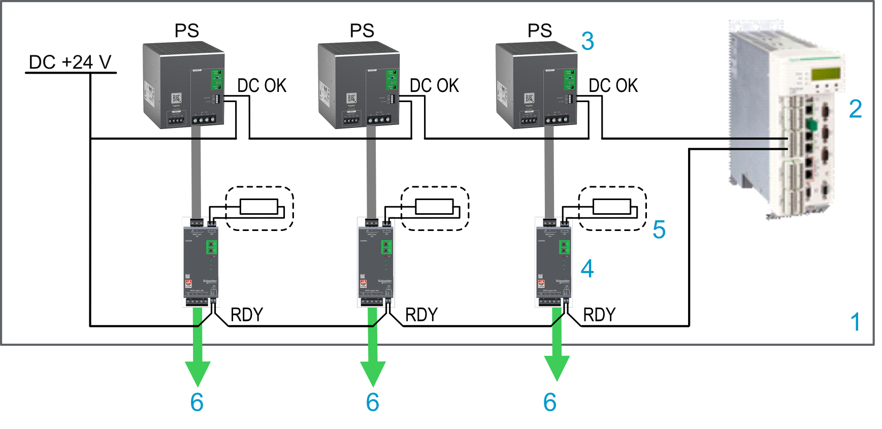
|
Element |
Description |
|---|---|
|
1 |
Control cabinet |
|
2 |
PacDrive LMC Pro2 Motion Controller |
|
3 |
Power supply |
|
4 |
Lexium™ MC connection module with RDY relay Normally Open (NO) output |
|
5 |
External braking resistor (optional) |
|
6 |
DC bus to the Lexium™ MC12 multi carrier track |
Status LEDs
Refer to connection module above.
|
Name |
Color |
Description |
On |
Slow flashing 2 Hz (1) |
Fast flashing 4 Hz (1) |
|---|---|---|---|---|---|
|
DC |
Green |
DC bus status |
Steady on: Input supply OK, 40.8...60 Vdc |
Undervoltage |
Overvoltage |
|
DC Err |
Red |
General error detected |
Steady on: Track could not be charged |
Undervoltage during operation detected, stored |
Incorrect setting of switches |
|
BR |
Green |
Braking resistor activated |
On for ≥ 500 ms: Braking resistor is activated |
– |
–(2) |
|
BR Err |
Red |
Braking resistor overload / short circuit |
Steady on: Braking resistor short circuit |
Braking resistor connection supervision (3) |
Braking resistor overload (I2t) |
|
(1) Switch off input voltage to acknowledge an error state:
(2) Invalid voltage selection on the Lexium™ MC connection module. (3) Braking resistor connection supervision:
|
|||||
Switches
Use the rotary switches (P1, P2) to set the parameters for the braking resistors. Refer to connection module above.
In the delivery state, both switches are set to the value zero.
Modifying the switch positions of P1 / P2 during operation may result in high temperatures and damage of the connection module and the braking resistor after the next power cycle of the module.
| WARNING | |
|---|---|
|
P1 (type) |
Braking resistor type |
P_Braking resistor [W] |
R_Braking resistor [Ω] |
Pulse energy capacity [J] |
|---|---|---|---|---|
|
0 |
Internal (default) |
10 |
1.56 |
60 |
|
2 |
External |
50 1) |
3.0 |
4000 |
|
4 |
External |
100 |
3.0 |
4000 |
|
6 |
External |
100 1) |
1.5 2) |
8000 |
|
8 |
External |
200 |
1.5 2) |
8000 |
|
1, 3, 5, 7, 9...E |
Not allowed. An error is indicated. |
– |
– |
– |
|
F |
Not allowed (special mode) |
– |
– |
– |
|
P_Braking = Continuous power value R_Braking = Resistance value 1) In this switch position, the continuous power is reduced to 50%, resulting in a lower surface temperature. 2) Two external 3 Ω braking resistors in parallel for higher peak and continuous power. |
||||
For the external braking resistor (LXMMCABR120S100), also refer to Technical Data for Lexium™ MC braking resistor.
|
P2 (level) |
Braking resistor voltage |
V_BR0 [V] |
V_BR1 [V] |
|---|---|---|---|
|
0 |
Increasing with load (default) |
52 |
56 |
|
1 |
Increasing with load |
54 |
58 |
|
2 |
Increasing with load |
56 |
60 |
|
3 |
Constant |
54 |
54 |
|
4 |
Constant |
56 |
56 |
|
5 |
Constant |
58 |
58 |
|
6 |
Constant |
60 |
60 |
|
7...E |
Not allowed. An error is indicated. |
– |
– |
|
F |
Not allowed. Braking resistor will be permanently off. |
– |
– |
|
Dynamic load-dependent switch-on threshold for the braking resistor: V_BR0 = Switch-on threshold value when the braking resistor is not yet loaded V_BR1 = Switch-on threshold value when the braking resistor is fully loaded at its power limit |
|||
Connecting a Braking Resistor (CN2)
An insufficiently rated braking resistor can cause overvoltage on the DC bus. Overvoltage on the DC bus causes the power stage to be disabled. The system is no longer actively decelerated.
| WARNING | |
|---|---|
During operation, the surface temperature of the housing of the Lexium™ MC connection module may exceed 70 °C (158 °F).
| WARNING | |
|---|---|
Internal braking resistor
A braking resistor is integrated in the Lexium™ MC connection module to absorb braking energy. The Lexium™ MC connection module is shipped with the internal braking resistor (10 W, continuous power) active (jumper between PA/+ and PBi).
External Braking Resistor
An external braking resistor is required for applications in which the internal resistor is not able to absorb the braking energy.
Remove the jumper between PA/+ and PBi and connect the external braking resistor between PA/+ and PBe. Refer to Technical Data for Lexium™ MC braking resistor.
During operation, the surface temperature of the external braking resistor may exceed 250 °C (482 °F).
| DANGER | |
|---|---|
Connecting an external braking resistor
| DANGER | |
|---|---|
|
Step |
Action |
|---|---|
|
1 |
Remove power from the supply voltages. Respect the safety instructions concerning electrical installation. |
|
2 |
Verify that no voltages are present. |
|
3 |
Remove the jumper between PA/+ and PBi and connect the external braking resistor between PA/+ and PBe to the Lexium™ MC connection module. |
|
4 |
If the braking resistor is equipped with an over temperature switch, it can be connected to the PacDrive LMC Pro2 Motion Controller for diagnostic purposes and to de-energize the power supply in case of overheat. Refer to Wiring Example (Connecting an External Braking Resistor) and Wiring Example (Shut Down). |
|
5 |
Use the switches P1 and P2 of the Lexium™ MC connection module to set the braking resistor type and the braking resistor voltage level. Refer to Switches. |
Monitoring of the Braking Resistor
The braking resistor (internal or external) is monitored by the Lexium™ MC connection module. In case of overload and short circuit, the connection module signals a detected error (BR Err, refer to Status LEDs) and opens the RDY relay.