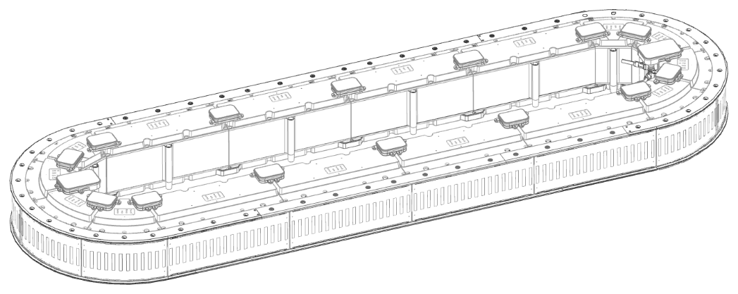
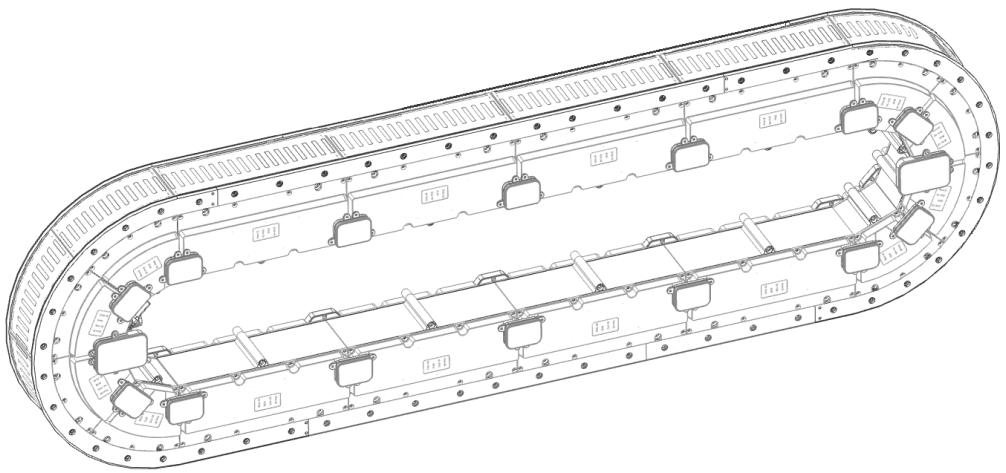
Mounting the Lexium™ MC12 multi carrier
Prerequisites
The following prerequisites must be met to mount your Lexium™ MC12 multi carrier:
-
The layout of your Lexium™ MC12 multi carrier is defined.
-
It is specified where the Lexium™ MC power cables, the Sercos cable, and SFO cables will be connected.
-
All components to build the requested system layout are available.
-
All components have the same temperature (for the storage temperature range, refer to Ambient Conditions).
-
The mounting plate for your system is prepared. Refer to chapter Mounting Plate.
| WARNING | |
|---|---|
Open Track
With an open track, the carriers could leave the track at the ends. Therefore, mechanical hard stops must be mounted at both ends of an open track.
| WARNING | |
|---|---|
Refer to Mounting the Hard Stops.
Mounting the Lexium™ MC12 multi carrier Track
The components of the Lexium™ MC12 multi carrier must be handled with care. Refer to Transport and Storage.
Lexium™ MC guide rails can bend if handled improperly and may then no longer be usable.
| NOTICE | |
|---|---|
Horizontal Mounting
|
Step |
Action |
|---|---|
|
1 |
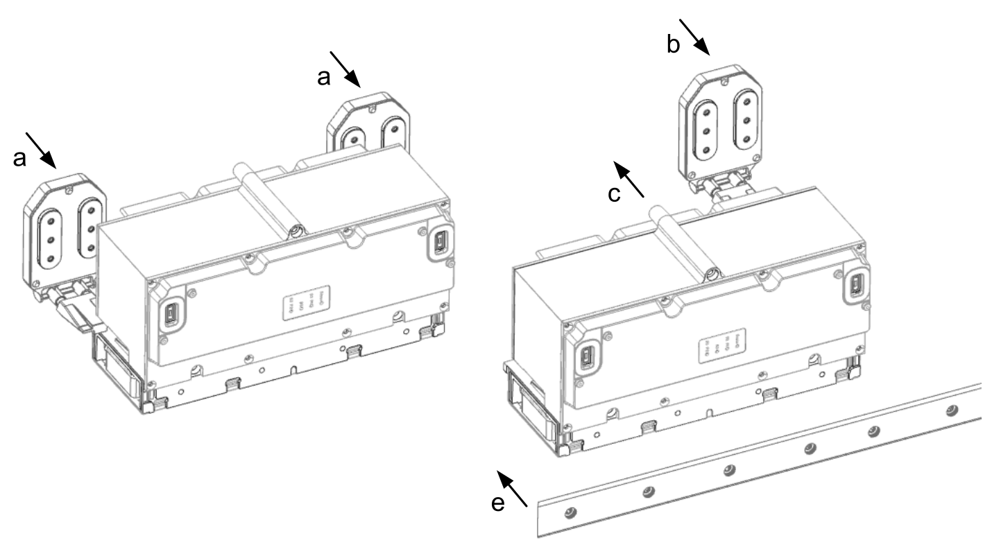
Place two Lexium™ MC power interconnects (a) at a distance of one segment length at the intended location on the mounting plate. 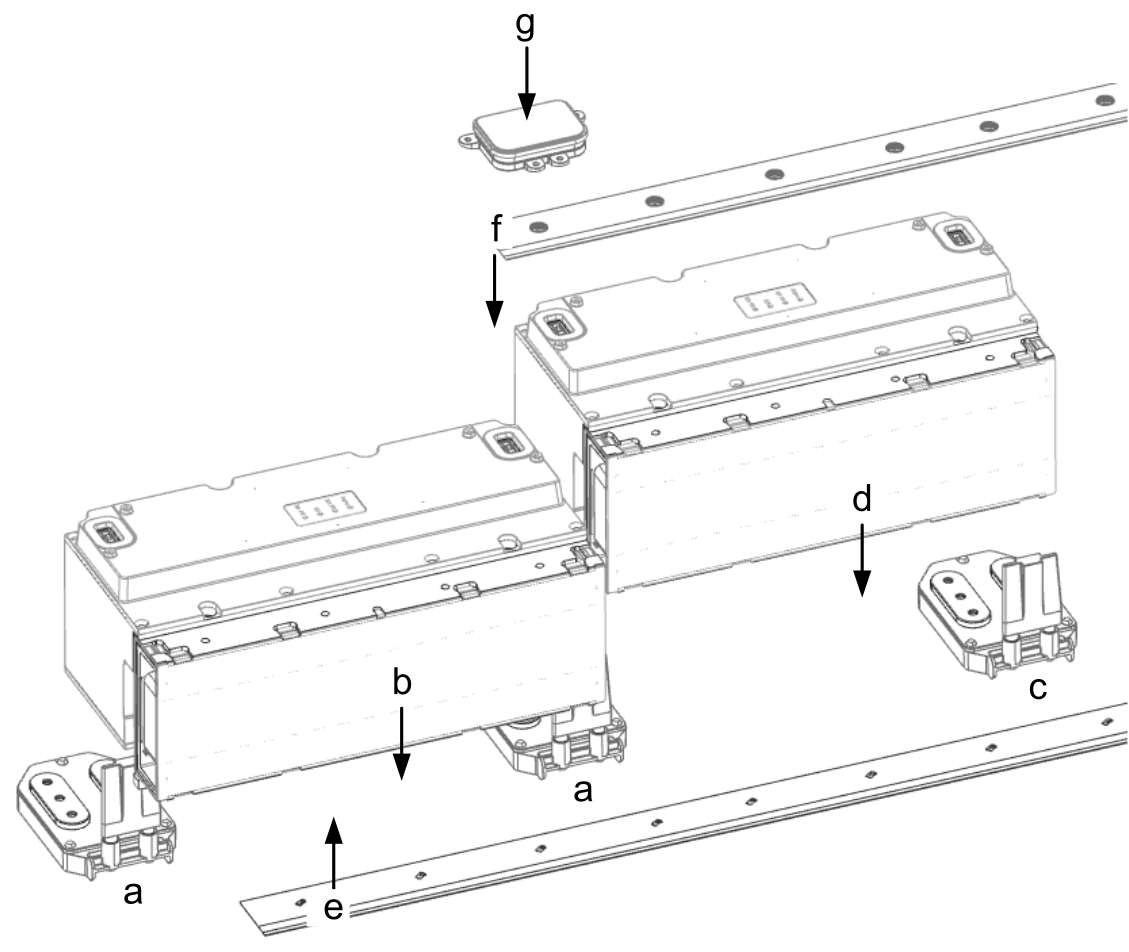
To achieve the correct distance between the interconnects, insert the three semi-circular positioning knobs on the bottom of the interconnects into the corresponding holes in the mounting plate. 
NOTE: If a power interconnect is used to supply your system with power from the control cabinet, use the respective reference of the Lexium™ MC power interconnects / Power disconnector.
|
|
2 |
Insert a segment (b) from above into the two interconnects. Make sure that the segment is not tilted during insertion. The alignment aid and the oval fitting of the power interconnects help you to join the segments in a straight alignment. Fasten the segment loosely with three screws (M6x120 class 8.8 ISO 4762) to the mounting plate so that it will stay in place but can still be shifted a little. |
|
3 |
Place the next Lexium™ MC interconnect (c) at a distance of one segment length at the intended location on the mounting plate. To achieve the correct distance between the interconnects, insert the three semi-circular positioning knobs on the bottom of the interconnect into the corresponding holes in the mounting plate. Insert a segment (d) from above into the two interconnects. Make sure that the segment is not tilted during insertion. The alignment aid and the oval fitting of the power interconnects help you to join the segments in a straight alignment. Fasten the segment loosely with three screws. |
|
4 |
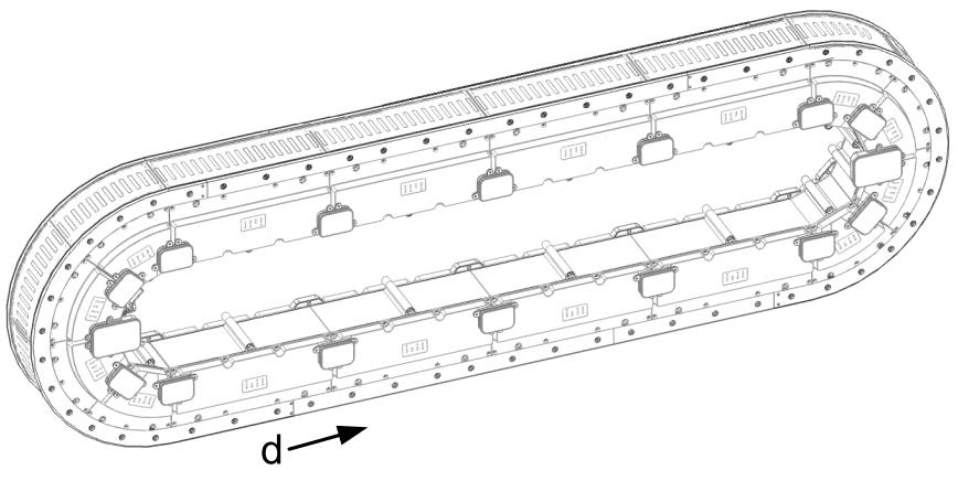
Proceed in the same way, using straight and arc segments to build your system layout. With an open track proceed as described under Hard Stops\Horizontal Mounting. |
|
5 |
When all the segments are in place, install the bottom Lexium™ MC guide rails (e), starting at an arc segment or at an open end of the track. The rails are mounted offset to the segments by design. |
|
6 |
Position a Lexium™ MC guide rail (e) under the segments and fasten the rail with the associated screws (M6x16 class 8.8 DIN 7984) loosely.
NOTE: Make sure that the holes in the rails exactly match the holes in the segments. Make sure that the rails are aligned with the segment stops.
|
|
7 |
Tighten the fastening screws of the rail at the first segment. |
|
8 |
Align next rail. Make sure that the rails fit closely together at the transition between two rails. For fine alignment of the rails, you can remove the M5 screws (set screws) closest to the transition and insert M5x20 screws. Make sure that you do not drive the screws in too deep: the screws must not have any contact with the support surface for the rails. Then slide a suitable mounting tool between the screws (in rail direction or across the rail direction) and carefully push the rails into the desired position. After fine alignment of the rails, replace the long M5 screws with the M5 set screws again. 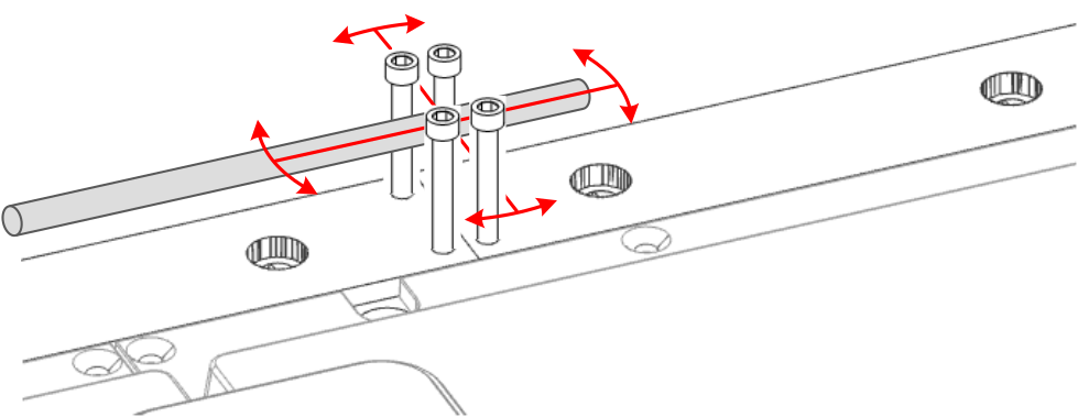
|
|
9 |
Tighten screws of both bottom rails at the segment the rails connect with a torque of 10.1 Nm (89.4 lbf-in). |
|
10 |
Proceed in the same way with the subsequent bottom rails until all bottom rails are installed. |
|
11 |
Repeat steps 5 - 10 for the corresponding top rails (f). |
|
12 |
If you need to adjust the height of a rail at the transition of two rails, unfasten the screws closest to the transition, adjust the two set screws (M5x8 ISO 4026) and fasten the rail again.
NOTE: Ensure that the height of the rails is accurately aligned to ensure smooth guidance of the carrier.
|
|
13 |
After you adjusted the height of the rails at the transition, tighten the first and the last fastening screws of the rail with a torque of 7.2 Nm (63.7 lbf-in). |
|
14 |
Repeat steps 12 - 13 for all bottom and top rails. |
|
15 |
Hand tighten the M5 set screws that were not used when adjusting the height of the rails (step 12). Make sure that they are screwed in completely. |
|
16 |
Tighten the rest of the guide rail screws with the a torque of 7.2 Nm (63.7 lbf-in). |
|
17 |
After you installed the rails, tighten the screws of the Lexium™ MC12 long stator motor segments with a torque of 10.1 Nm (89.4 lbf-in). Result: The Lexium™ MC12 multi carrier track is fixed. |
|
18 |
Insert the Lexium™ MC communication interconnects (g) from top between the segments. Fix the communication interconnect with its four corresponding screws (M3x8 ISO 14583) with a torque of 0.6 Nm (5.31 lbf-in).
NOTE: If such a communication interconnect is used to connect the system with the Sercos bus and/or an SFO (Safe Force Off) control device, use the respective reference of the Lexium™ MC communication interconnects.
|
|
19 |
Use the Lexium™ MC power cables, the Sercos cable, and the SFO cables to connect your Lexium™ MC12 multi carrier with the control cabinet. For details, refer to chapter Electrical Installation. Result: The Lexium™ MC12 multi carrier track is installed and ready for verification. Also refer to Verifying the Installation. |
Vertical Mounting
|
Step |
Action |
|---|---|
|
1 |
Insert two Lexium™ MC power interconnects (a) into a segment sideways. Make sure that the power interconnects are not tilted during insertion.
NOTE: If a power interconnect is used to supply your system with power from the control cabinet, use the respective reference of the Lexium™ MC power interconnects / Power disconnector.
|
|
2 |
Fasten the segment loosely with three screws (M6x120 class 8.8 ISO 4762) to the mounting plate so that it will stay in place but can still be shifted a little. To achieve the correct distance between the interconnects, insert the three semi-circular positioning knobs on the bottom of the interconnects into the corresponding holes in the mounting plate.
|
|
3 |
Insert one Lexium™ MC interconnect (b) into another segment. |
|
4 |
Insert the segment (c) sideways into the power interconnect of the already mounted segment.
NOTE: It is a good practice to start with the lower left straight segment (d).
|
|
5 |
Fasten the segment loosely with three screws to the mounting plate so that it will stay in place but can still be shifted a little. |
|
6 |
Proceed in the same way, using straight and arc segments to build your system layout. With an open track proceed as described under Mounting the Hard Stops\Vertical Mounting. |
|
7 |
When all the segments are in place, tighten the screws of the segments with a torque of 10.1 Nm (89.4 lbf-in). |
|
8 |
After all segments are in place and screwed tight, install the top Lexium™ MC guide rails (e), starting in the middle of your track (f) or at an open end of the track. The rails are mounted offset to the segments by design. 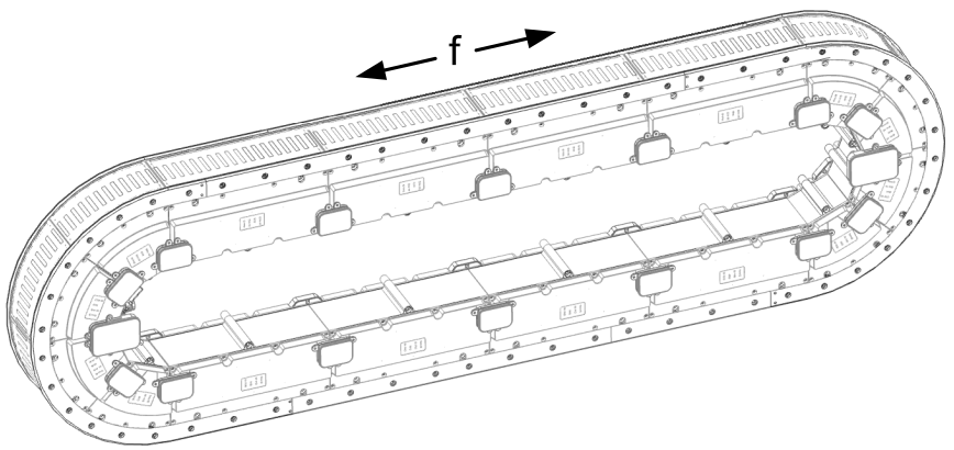
|
|
9 |
Position a Lexium™ MC guide rail on the segments and fasten the rail with the associated screws (M6x16 class 8.8 DIN 7984) loosely.
NOTE: Make sure that the holes in the rails exactly match the holes in the segments. Make sure that the rails are aligned with the segment stops.
|
|
10 |
Proceed in the same way with the subsequent top rails until all top rails are installed. |
|
11 |
Repeat steps 9 - 10 for the corresponding bottom rails. Result: The top rails and the bottom rails are in place. |
|
12 |
Start aligning all straight top rails from the inside to the outside. (f). |
|
13 |
Align the two rails at the middle segment. Make sure that the rails fit closely together at the transition between two rails. For fine alignment of the rails, you can remove the M5 screws (set screws) closest to the transition and insert M5x20 screws. Make sure that you do not drive the screws in too deep: the screws must not have any contact with the support surface for the rails. Then slide a suitable mounting tool between the screws (in rail direction or across the rail direction) and carefully push the rails into the desired position. After fine alignment of the rails, replace the long M5 screws with the M5 set screws again. 
|
|
14 |
If you need to adjust the height of a rail at the transition of two rails, unfasten the screws closest to the transition, adjust the two set screws (M5x8 ISO 4026) and fasten the rail again.
NOTE: Make sure that the height of the rails is accurately aligned to ensure smooth guidance of the carrier.
|
|
15 |
After you adjusted the height of the rails at the transition, tighten the first and the last fastening screws of the rail with a torque of 7.2 Nm (63.7 lbf-in).
NOTE: Hand tighten the M5 set screws that were not used when adjusting the height of the rails. Make sure that they are screwed in completely.
|
|
16 |
Proceed in the same way with the subsequent straight top rails until all straight top rails are aligned. |
|
17 |
Proceed in the same way with the straight bottom rails. |
|
18 |
After aligning the straight rails, align the arc rails in the same way. |
|
19 |
After aligning all rails, tighten the remaining fastening screws of all rails with a torque of 7.2 Nm (63.7 lbf-in). |
|
20 |
Insert the Lexium™ MC communication interconnects (g) sideways between the segments. Fix the communication interconnect with its four corresponding screws (M3x8 ISO 14583) with a torque of 0.6 Nm (5.31 lbf-in). 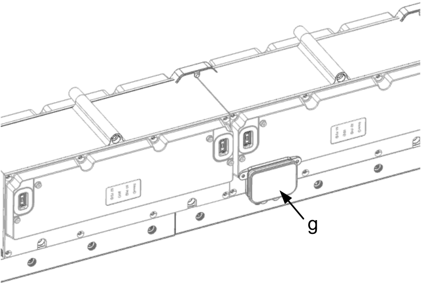
NOTE: If such a communication interconnect is used to connect the system with the Sercos bus and/or an SFO (Safe Force Off) control device, use the respective reference of the Lexium™ MC communication interconnects.
|
|
21 |
Use the Lexium™ MC power cables, the Sercos cable, and the SFO cables to connect your Lexium™ MC12 multi carrier with the control cabinet. For details, refer to chapter Electrical Installation. Result: The Lexium™ MC12 multi carrier track is installed and ready for verification. Also refer to Verifying the Installation. |
| DANGER | |
|---|---|
Mounting the Hard Stops
With an open track, the carriers could leave the track at the ends. Therefore, mechanical hard stops must be mounted at both ends of an open track.
Mounting of the hard stops is carried out similarly to the mounting of the track (Mounting the Lexium™ MC12 multi carrier).
Horizontal Mounting
|
Step |
Action |
|---|---|
|
1 |
After mounting the power interconnects (a) and the segments (b), insert a left hard stop (c) from above into the left power interconnect and a right hard stop (d) into the right power interconnect. 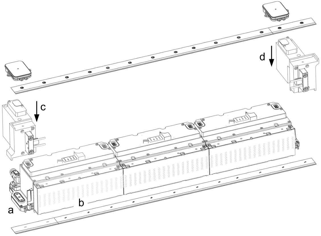
|
|
2 |
Fasten the hard stops loosely with two screws (M6x120 class 8.8 ISO 4762) to the mounting plate so that they stay in place but can still be shifted a little. |
|
3 |
Then proceed as described from step 5 in the section Mounting the Lexium™ MC12 multi carrier Track\Horizontal mounting above. |
|
Step |
Action |
|---|---|
|
1 |
After mounting the power interconnects (a) and the segments (b), insert a left hard stop (c) from above into the left power interconnect and a right hard stop (d) into the right power interconnect. 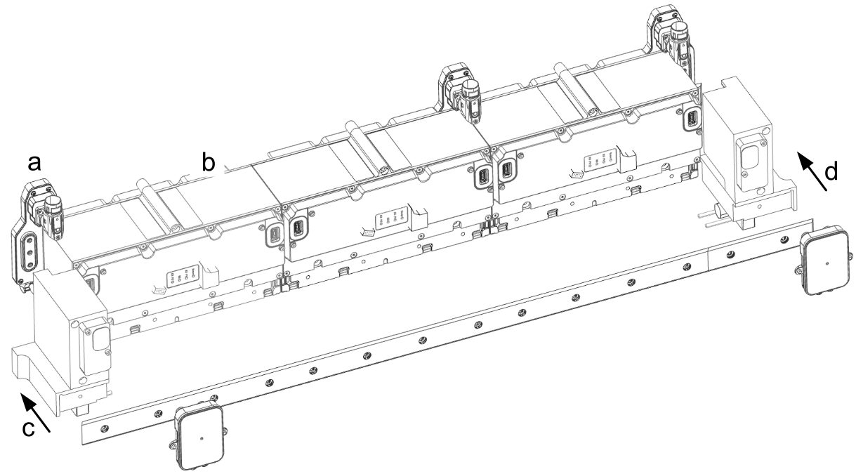
|
|
2 |
Fasten the hard stops loosely with two screws (M6x120 class 8.8 ISO 4762) to the mounting plate so that they stay in place but can still be shifted a little. |
|
3 |
Then proceed as described from step 7 in the section Mounting the Lexium™ MC12 multi carrier Track\Vertical mounting above. |