IO0_Mode ... IO7_Mode
Functional Description
Defines the input/output mode.
|
Value |
Meaning |
|---|---|
|
inactive / 0 |
The input/output is switched off. |
|
Input / 1 |
Only the static state of the input (Value parameter) can be queried. |
|
Output / 2 |
Output function. |
|
Touchprobe / 3 |
The touchprobe function is activated. See also the CaptureState, CaptureOK, CaptureValue, and SensorDelay parameters. |
|
Fast counter / 4 |
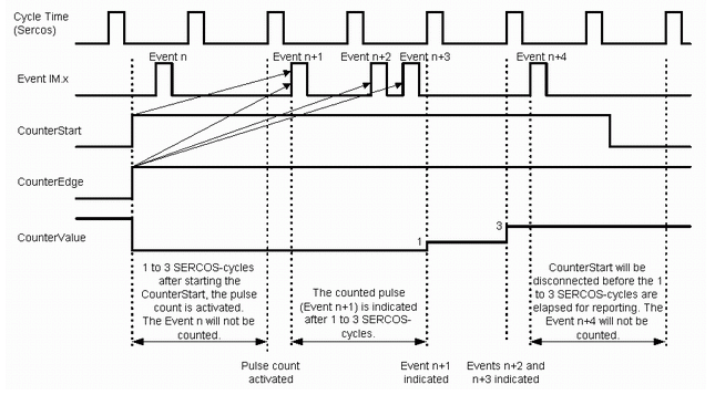
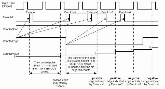
The impulse counter function is activated. See also CounterState, CounterValue, CounterStart, and CounterEdge |
8787 Configuration error is triggered.
Touchprobe
The TouchProbe functions are measuring functions. They accurately detect positions relative to a measure input.
Impulse Counter (Fast Counter)
The impulse counter is a measuring function that allows fast impulses to be recorded and counted at the measured inputs. Once an impulse counter has been enabled, it runs in the system independently of the program. The program can use parameters to determine the status of the counting function.
For more information on the accuracy of the measuring inputs, see the description of the CaptureValue parameter of the digital measuring inputs.
Minimum Length of a Measuring Impulse
The shortest time of a high impulse is 100 µs; the shortest time of a low impulse is 230 µs. This yields a maximum frequency of approximately 3 kHz. For a pulse/pause ratio of 1:1, a maximum frequency of approximately 2.2 kHz can be reached.

