Additional signal sequence diagrams
Temporary intermediate states are not illustrated in the signal sequence diagrams. Only typical input signal combinations are illustrated in these diagrams. Other signal combinations are possible.
The most significant areas within the signal sequence diagrams are highlighted in color.
Refer also to the diagram found in the overview for this function block.
The signal sequence diagrams in this documentation possibly omit particular diagnostic codes. For example, a diagnostic code is possibly not shown if the related function block state is a temporary transition state and only active for one cycle of the Safety Logic Controller.
Only typical input signal combinations are illustrated. Other signal combinations are possible.
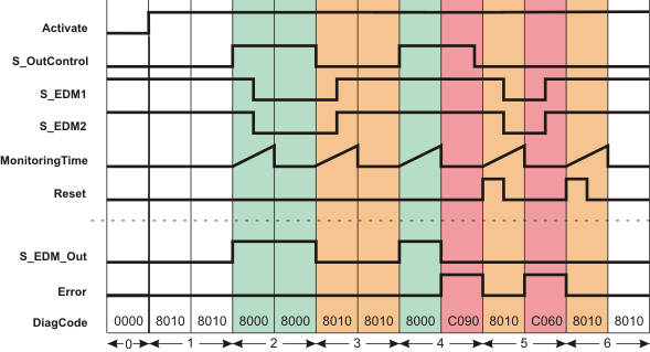
Device monitoring, no start-up inhibit after Safety Logic Controller start-up/function block activation (S_StartReset = SAFETRUE)
|
0 |
The function block is not yet activated (Activate = FALSE). As a result, all outputs are FALSE or SAFEFALSE. |
|
1 |
As parameter S_StartReset = SAFETRUE, no start-up inhibit is active after the function block has been activated. Output S_EDM_Out is SAFEFALSE, as input S_OutControl = SAFEFALSE. |
|
2 |
Output S_EDM_Out = SAFETRUE due to a SAFETRUE at S_OutControl and at S_EDM1 and S_EDM2 (initial state of the connected contactors). The timer set at MonitoringTime starts with the state change at S_EDM_Out. S_EDM1 and S_EDM2 switch to SAFEFALSE during the monitoring time (switching states of the connected contactors). Output S_EDM_Out remains SAFETRUE, as long as input S_OutControl = SAFETRUE. |
|
3 |
Output S_EDM_Out = SAFEFALSE due to a SAFEFALSE at S_OutControl. The timer set at MonitoringTime starts with the state change at S_EDM_Out. S_EDM1 and S_EDM2 switch to SAFETRUE during the monitoring time (initial state of the connected contactors). |
|
4 |
Output S_EDM_Out = SAFETRUE due to a SAFETRUE at S_OutControl and at S_EDM1 and S_EDM2 (initial state of the connected contactors). The timer set at MonitoringTime starts with the state change at S_EDM_Out. S_EDM1 and S_EDM2 do not switch to SAFEFALSE during the monitoring time (this is incorrect - error state). After the time set at MonitoringTime has elapsed, output Error = TRUE and S_EDM_Out = SAFEFALSE. |
|
5 |
When the FALSE > TRUE edge applies at the Reset input, the error message is reset and the time set at MonitoringTime for the two inputs S_EDM1 and S_EDM2 is started. S_EDM1 and S_EDM2 incorrectly switch to SAFEFALSE during the monitoring time. After the time set at MonitoringTime has elapsed, Error = TRUE and S_EDM_Out remains SAFEFALSE, since, if S_OutControl = SAFEFALSE, the initial state of the connected contactors is expected before the monitoring time expires. |
|
6 |
When the FALSE > TRUE edge applies at the Reset input, the error message is reset and the time set at MonitoringTime for the two inputs S_EDM1 and S_EDM2 is started. The monitoring time expires without result, as inputs S_EDM1 and S_EDM2 are both SAFETRUE. |