Additional application example
This documentation refers to the monitored electro-sensitive protective equipment as ESPE for short.
This section contains information on another possible application in which the function block can be used for monitoring ESPE.
The function block must only be used in an actual application once a risk analysis has been conducted.
Details of the risk category/SIL/PL have not been included here, as classification is always based on the application in which the function block is used.
The use of the function block alone is not sufficient to execute the safety-related function according to the Cat./SIL/PL determined by the risk analysis. In conjunction with the safety-related I/O device used, additional measures must be taken to meet the requirements of the safety-related function. These include, for example, the appropriate wiring and parameterization of the inputs and outputs as well as measures to exclude (design out) errors that cannot be detected. For additional information, refer to the documentation provided with the safety-related I/O device used.
Refer to the notes in the User Manual on proper electrical connection of the Safety Logic Controller and the extension modules (e.g., connecting the ESPE).
Refer also to the application example found in the overview for this function block.
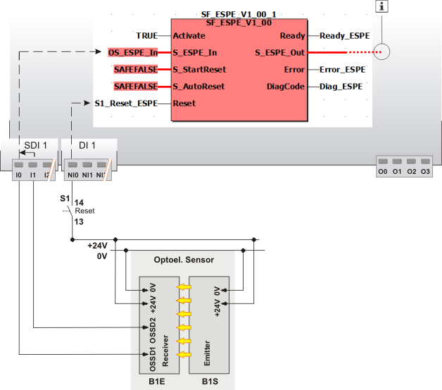
ESPE, two-channel, with start-up and restart inhibit
This example shows a two-channel connection between ESPE signals OSSD1 and OSSD2 and the safety-related SF_ESPE function block. The ESPE is connected to input terminals I0 and I1 of the safety-related input device SDI with the ID of 1.
The signal from the ESPE is evaluated, based on two channels, for equivalence in the safety-related input device, which has been parameterized accordingly. The resulting signal is assigned to the global I/O variable OS_ESPE_In. This global I/O variable is connected to the S_ESPE_In input of the function block for evaluation. It is SAFETRUE if both inputs of the safety-related input device SDI 1 are TRUE at the same time (ESPE not triggered) and the input device does not report any errors as regards exceeding the discrepancy time. For more detailed information, refer to the descriptions of the input channel parameters of the safety-related input device.
The function block is perpetually activated by a TRUE constant at the Activate input.
S_StartReset = SAFEFALSE specifies a start-up inhibit after the Safety Logic Controller has been started up or the function block has been activated. Furthermore, S_AutoReset = SAFEFALSE is used for specifying a restart inhibit for the function block, which is activated once the ESPE that was previously triggered is no longer triggered, i.e., once the SAFETRUE signal has returned at the S_ESPE_In input. Both inhibits are only removed when there is a positive signal edge at the Reset input.
To this end, the S1 reset button is connected to input NI0 of the standard input device DI 1.
The S_ESPE_Out enable output of the SF_ESPE function block is connected to an output terminal of the application via a global I/O variable or via other safety-related functions/function blocks.
Connect the S_ESPE_Out enable output of the SF_ESPE function block to the S_OutControl input of the SF_EDM function block, for example, thus implementing a two-channel output connection.
For more detailed information, refer to the description of the corresponding safety-related function block.
|
S1 |
Reset |
|
B1 |
ESPE |
|
B1S |
Emitter |
|
B1E |
Receiver |
|
|
See note above the illustration. |
