Additional signal sequence diagrams
Temporary intermediate states are not illustrated in the signal sequence diagrams. Only typical input signal combinations are illustrated in these diagrams. Other signal combinations are possible.
The most significant areas within the signal sequence diagrams are highlighted in color.
Refer also to the diagram found in the overview for this function block.
The signal sequence diagrams in this documentation possibly omit particular diagnostic codes. For example, a diagnostic code is possibly not shown if the related function block state is a temporary transition state and only active for one cycle of the Safety Logic Controller.
Only typical input signal combinations are illustrated. Other signal combinations are possible.
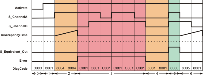
Exceeding the discrepancy time
|
0 |
The function block is not yet activated (Activate = FALSE). As a result, all outputs are FALSE or SAFEFALSE. |
|
1 |
Function block activation (Activate = TRUE) during which SAFEFALSE is present at both the S_ChannelA and S_ChannelB inputs. |
|
2 |
S_ChannelA switches to SAFETRUE. This starts measurement of the discrepancy time. Once the time set at DiscrepancyTime has elapsed, the inputs have different states. This results in an error message (Error output = TRUE). The S_EquivalentOut output remains in the defined safe state (SAFEFALSE). |
|
3 |
Irrespective of the states at the S_ChannelA and S_ChannelB inputs, the S_EquivalentOut output remains SAFEFALSE for as long as the error message is active (Error = TRUE). |
|
4 |
The Error output switches to FALSE again (error message is removed) as both inputs are now SAFEFALSE. |
|
5 |
S_EquivalentOut becomes SAFETRUE as both inputs S_ChannelA and S_ChannelB both become SAFETRUE at the same time. |
|
6 |
S_EquivalentOut switches to SAFEFALSE, as S_ChannelA switches to SAFEFALSE. The discrepancy time measurement starts when the state at S_ChannelA switches. S_EquivalentOut remains SAFEFALSE, as S_ChannelB also switches to SAFEFALSE within the time set at DiscrepancyTime. |