Additional application examples
This section describes other possible applications where the safety-related SF_GuardMonitoring function block could be used to monitor a guard (such as a door) with a two-stage interlocking system according to EN 1088.
The function block may only be used in an actual application once a risk analysis has been conducted.
Details of the risk category/SIL/PL have not been included here, as classification is always based on the application in which the function block is used.
The use of the function block alone is not sufficient to execute the safety-related function according to the Cat./SIL/PL determined by the risk analysis. In conjunction with the safety-related I/O device used, additional measures must be taken to meet the requirements of the safety-related function. These include, for example, the appropriate wiring and parameterization of the inputs and outputs as well as measures to exclude (design out) errors that cannot be detected. For additional information, refer to the documentation provided with the safety-related I/O device used.
Refer to the notes in the User Manual on proper electrical connection of the Safety Logic Controller and the extension modules (e.g., connecting the door).
Refer also to the application example found in the overview for this function block.
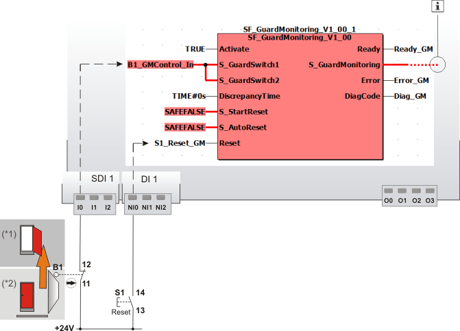
Door monitoring using a mechanical position switch (1 N/C contact), start-up inhibits active
This example describes how a mechanically activated position switch (1 N/C contact) is evaluated using the safety-related SF_GuardMonitoring function block. Position switch B1 is connected to input terminal I0 of the safety-related input device SDI 1.
The signal resulting from input terminal I0 is assigned to the global I/O variable B1_GMControl_In. This is connected to the safety-related SF_GuardMonitoring function block for evaluation.
Since only one signal reports the status of the door in this example (one position switch), this is connected in parallel to both inputs S_GuardSwitch1 and S_GuardSwitch2. In this case, a value of 0 seconds is set at input DiscrepancyTime.
The constant TRUE at the Activate input causes the safety-related SF_GuardMonitoring function block to be permanently activated.
S_StartReset = SAFEFALSE specifies a start-up inhibit after the Safety Logic Controller has been started up or the function block has been activated. Furthermore, S_AutoReset = SAFEFALSE specifies a restart inhibit for the function block after the door has been closed. Both inhibits are only removed when there is a positive signal edge at the Reset input.
To this end, the S1 reset button is connected to input terminal NI0 of the standard input device DI 1. The terminal is assigned to the global I/O variable S1_Reset_GM, which in turn is connected to the Reset input.
The enable signal at the S_GuardMonitoring output is connected to additional safety-related function blocks or functions and controls the application accordingly.
|
S1 |
Reset |
|
B1 |
Positively driven door switch/position switch
for positive opening operation |
|
(*1) |
Door: open |
|
(*2) |
Door: closed |
|
|
See note above the illustration. |
 (SAFETRUE, if safety equipment closed).

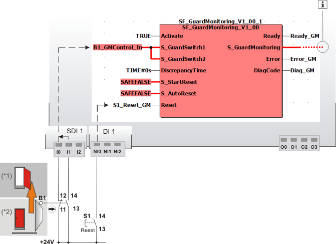
Door monitoring using a mechanical position switch (1 N/C contact, 1 N/O contact), start-up inhibits active
This example describes how a mechanically activated position switch with one N/C contact and one N/O contact is evaluated using the safety-related SF_GuardMonitoring function block. Position switch B1 is connected to input terminals I0 and I1 of safety-related input device SDI 1.
The signals from position switch B1 are evaluated, based on two channels, for antivalence in the safety-related input device, which has been parameterized accordingly. The resulting signal is assigned to the global I/O variable B1_GMControl_In. This global I/O variable is connected to the inputs S_GuardSwitch1 and S_GuardSwitch2 of the SF_GuardMonitoring function block for evaluation.
B1_GMControl_In is SAFETRUE if the signal of the N/C contact is SAFETRUE and the signal of the N/O contact is SAFEFALSE (safety equipment closed) and there is no error message as a result of the discrepancy time being exceeded.
Since only one signal reports the status of the door in this example (one position switch), this is connected in parallel to both inputs S_GuardSwitch1 and S_GuardSwitch2. In this case, a time of 0 seconds must be set at DiscrepancyTime.
The function block is perpetually activated by a TRUE constant at the Activate input.
S_StartReset = SAFEFALSE specifies a start-up inhibit after the Safety Logic Controller has been started up or the function block has been activated. Furthermore, S_AutoReset = SAFEFALSE specifies a restart inhibit for the function block after the door has been closed. Both inhibits are only removed when there is a positive signal edge at the Reset input.
To this end, the S1 reset button is connected to input terminal NI0 of the standard input device DI 1. The terminal is assigned to the global I/O variable S1_Reset_GM, which in turn is connected to the Reset input.
The enable signal at the S_GuardMonitoring output of the safety-related SF_GuardMonitoring function block is connected to additional safety-related function blocks or functions and controls the application accordingly.
|
S1 |
Reset |
|
B1 |
Door switch with one positively driven N/C contact
for positive opening operation |
|
(*1) |
Door: open |
|
(*2) |
Door: closed |
|
|
See note above the illustration. |
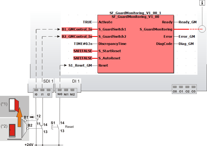
Door monitoring using two different mechanical position switches (1 x N/C contact, 1 x N/O contact), start-up inhibits active
This example describes how two mechanically activated position switches are evaluated using the safety-related SF_GuardMonitoring function block. Position switch B1 has one N/C contact and position switch B2 has one N/O contact.
B1 and B2 are connected to input terminals I0 and I1 of safety-related input device SDI 1.
-
The signal of the input terminal I0 of the safety-related input device SDI 1 is assigned to the global I/O variable B1_GMControl_In. This is connected to the S_GuardSwitch1 input of the function block for evaluation.
-
Likewise, the following applies to the signal of the second position switch: The signal of the input terminal I1 of the safety-related input device SDI 1 is assigned to the global I/O variable B2_GMControl_In. This is connected to the S_GuardSwitch2 input of the function block for evaluation.
The constant TRUE at the Activate input causes the safety-related SF_GuardMonitoring function block to be permanently activated.
S_StartReset = SAFEFALSE specifies a start-up inhibit after the Safety Logic Controller has been started up or the function block has been activated. Furthermore, S_AutoReset = SAFEFALSE specifies a restart inhibit for the function block after the door has been closed. Both inhibits are only removed when there is a positive signal edge at the Reset input.
To this end, the S1 reset button is connected to input terminal NI0 of the standard input device DI 1. The terminal is assigned to the global I/O variable S1_Reset_GM, which in turn is connected to the Reset input.
The enable signal at the S_GuardMonitoring output of the safety-related SF_GuardMonitoring function block is connected to additional safety-related function blocks or functions and controls the application accordingly.
|
S1 |
Reset |
|
B1 |
Door switch with one positively driven N/C contact
for positive opening operation |
|
B2 |
Door switch, 1 N/O contact (SAFETRUE if safety equipment closed). |
|
(*1) |
Door: open |
|
(*2) |
Door: closed |
|
|
See note above the illustration. |
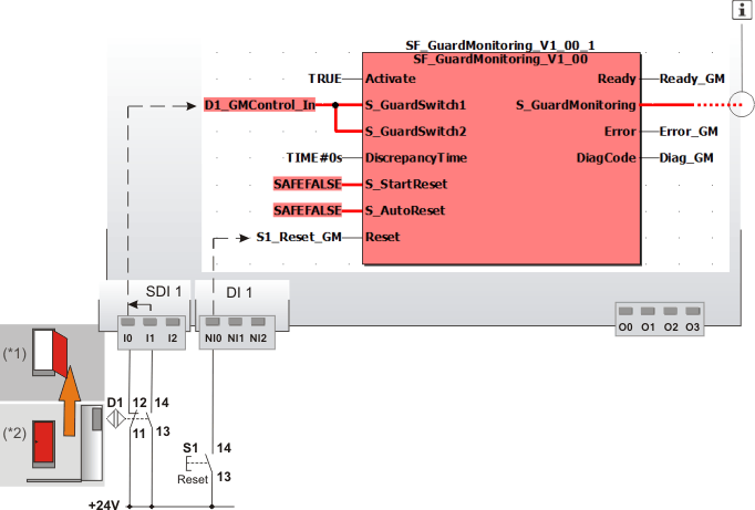
Door monitoring using an electronic position switch with an N/O and N/C combination, start-up inhibits active
This example describes how a two-channel, contact-free, magnetic position switch (N/O and N/C combination) is evaluated using the safety-related SF_GuardMonitoring function block. Position switch D1 is connected to input terminals I0 and I1 of safety-related input device SDI 1.
The signals from the electronic position switch D1 are evaluated, based on two channels, for antivalence in the safety-related input device, which has been parameterized accordingly. The resulting signal is assigned to the global I/0 variable D1_GMControl_In. This is connected to the inputs S_GuardSwitch1 and S_GuardSwitch2 of the safety-related SF_GuardMonitoring function block for evaluation.
D1_GMControl_In is SAFETRUE if the signal of the N/C contact is SAFETRUE and the signal of the N/O contact is SAFEFALSE (safety equipment closed) and there is no error message as a result of the time set at DiscrepancyTime being exceeded.
Since only one signal reports the status of the door in this example (one position switch), this is connected in parallel to both inputs S_GuardSwitch1 and S_GuardSwitch2. In this case, a value of 0 seconds is set at input DiscrepancyTime.
The function block is perpetually activated by a TRUE constant at the Activate input.
S_StartReset = SAFEFALSE specifies a start-up inhibit after the Safety Logic Controller has been started up or the function block has been activated. Furthermore, S_AutoReset = SAFEFALSE specifies a restart inhibit for the function block after the door has been closed. Both inhibits are only removed when there is a positive signal edge at the Reset input.
To this end, the S1 reset button is connected to input terminal NI0 of the standard input device DI 1. The terminal is assigned to the global I/O variable S1_Reset_GM, which in turn is connected to the Reset input.
|
S1 |
Reset |
|
D1 |
Contact-free magnetic switch with a separate actuation element. The graphic shows the state when the safety equipment is closed and the actuation element is located upstream of the sensor/evaluation unit. |
|
(*1) |
Door: open |
|
(*2) |
Door: closed |
|
|
See note above the illustration. |