SMC_ToolRadiusCorr (FB)
FUNCTION_BLOCK SMC_ToolRadiusCorr
SMC_ToolRadiusCorr creates a shifted path. In the shifted path, each point has a defined distance to the original point (tool radius correction). A typical application is the milling of a programmed contour with a milling drill of a certain diameter. In order to compensate the radius of the drill, the milling drill must follow a shifted path.
This function block replaces SMC_ToolCorr. The main feature is to also support 3d-movements and to respect the current correction plane (i.e. at decoding time the plane that circles would be defined in). We always use SMC_TOOLCORRMODE.TC_RAMP_IN, so the input eMode is no longer necessary.
Tool radius correction is controlled by the g-code: G41 (G42) starts correction to the left (right), G40 ends it.
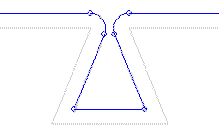
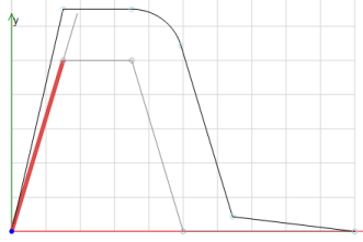
Example 1: Simple tool radius correction
G-Code
N0 G41 D3 (start correction)
N1 G1 X3 Y10 F100 E1000 E-1000
N2 G1 X7 Y10
N3 G1 X10 Y0
N4 G40 (end correction)
N5 G1 X20
In the above example, the element in sentence N1 is used for ramping in, the one in sentence N5 for ramping out.
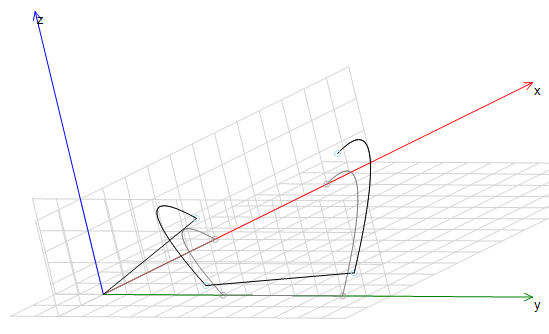
Example 2: Tool radius correction in different planes
G-Code
N0 G41 D1 F100 (start correction)
N1 G16 I1 J1 K1 (change correction plane)
N2 G1 X5
N3 G2 X0 Y5 R5
N4 G42 D1 (change sides)
N5 G16 I1 J1 K-1 (change correction plane)
N6 G1 Y10
N7 G3 X10 Y0 R15
The above example shows how tool radius correction may work in different planes. The correction plane is changed with G16. The element in sentence N6 is used for transitioning.
At inside corners, the projections of the corrected (shifted) elements onto the correction plane will usually intersect and we shorten those elements accordingly. Concerning the component which is perpendicular to the correction plane (z when correcting in the xy plane), the new meeting point will equal the original one. Same for additional axes.
G75 during tool radius correction is not supported: The correction of one element strongly depends on the following, which can't be known if there is a G75 in between. A G75 must not follow a G40, either: The first movement after G40 is used for ramping out and therefore still "belongs" to the correction block. For the same reason, we get in trouble if the in-queue is full without containing a second cartesian element (e.g. only M-functions), and also return an error.
If the correction radius or the correction plane or the correction side (left or right) changes from one element to the other, we will act like at the beginning of tool correction and use the element with the new parameters for ramping in.
Changing the planes during tool correction are not supported Jumps (G92 or implicitly by G43) during tool correction are not supported. Splines with degree 5, as created by SMC_SmoothPath or SMC_SmoothMerge, are not supported yet.
| InOut: |
|