FB_ExecuteAbort
Functional Description
The function block FB_ExecuteAbort provides the common behavior and the common inputs and outputs for implementing a function block, according to definition used for tasks that are executed once with a defined final state and the possibility to abort the ongoing execution.
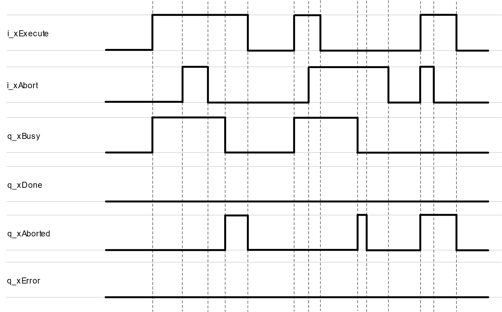
A rising edge of the input i_xExecute starts the execution of the function block. The function block continues execution and the output q_xBusy is set to TRUE. A rising edge of the input i_xExecute is ignored while the function block is being executed.
A rising edge of the input i_xAbort aborts the execution of the function block. As soon as the abort procedure has been finished, the output q_xAborted is set to TRUE.
Once the execution or abort procedure is finished, one of the outputs q_xDone, q_xError or q_xAborted remains TRUE until the input i_xExecute is set to FALSE. If the input is reset before the execution is finished, the output q_xDone, q_xError or q_xAborted is set to TRUE for one cycle. One cycle indicates the period until the next call of the function block.
Interface
|
Input |
Data type |
Description |
|---|---|---|
|
i_xExecute |
BOOL |
A rising edge of this input starts the execution of the function block. |
|
i_xAbort |
BOOL |
A rising edge of this input aborts the execution of the function block. |
|
Output |
Data type |
Description |
|---|---|---|
|
q_xBusy |
BOOL |
If this output is set to TRUE, the function block execution is in progress. |
|
q_xDone |
BOOL |
If this output is set to TRUE, the execution has been completed successfully. |
|
q_xAborted |
BOOL |
If this output is set to TRUE, the execution has been aborted. |
|
q_xError |
BOOL |
If this output is set to TRUE, an error has been detected. |
The function block FB_ExecuteAbort provides the properties timTimeout and xTimeoutExpired. For a description, refer to the chapter Properties.
Signal Diagrams
The signal diagram for successful execution is identical with the signal diagram during successful execution of the function block FB_Execute.
Signal diagram for successfully aborting the ongoing execution:

Signal diagram for detecting an error while aborting the ongoing execution:

State Machine Diagram
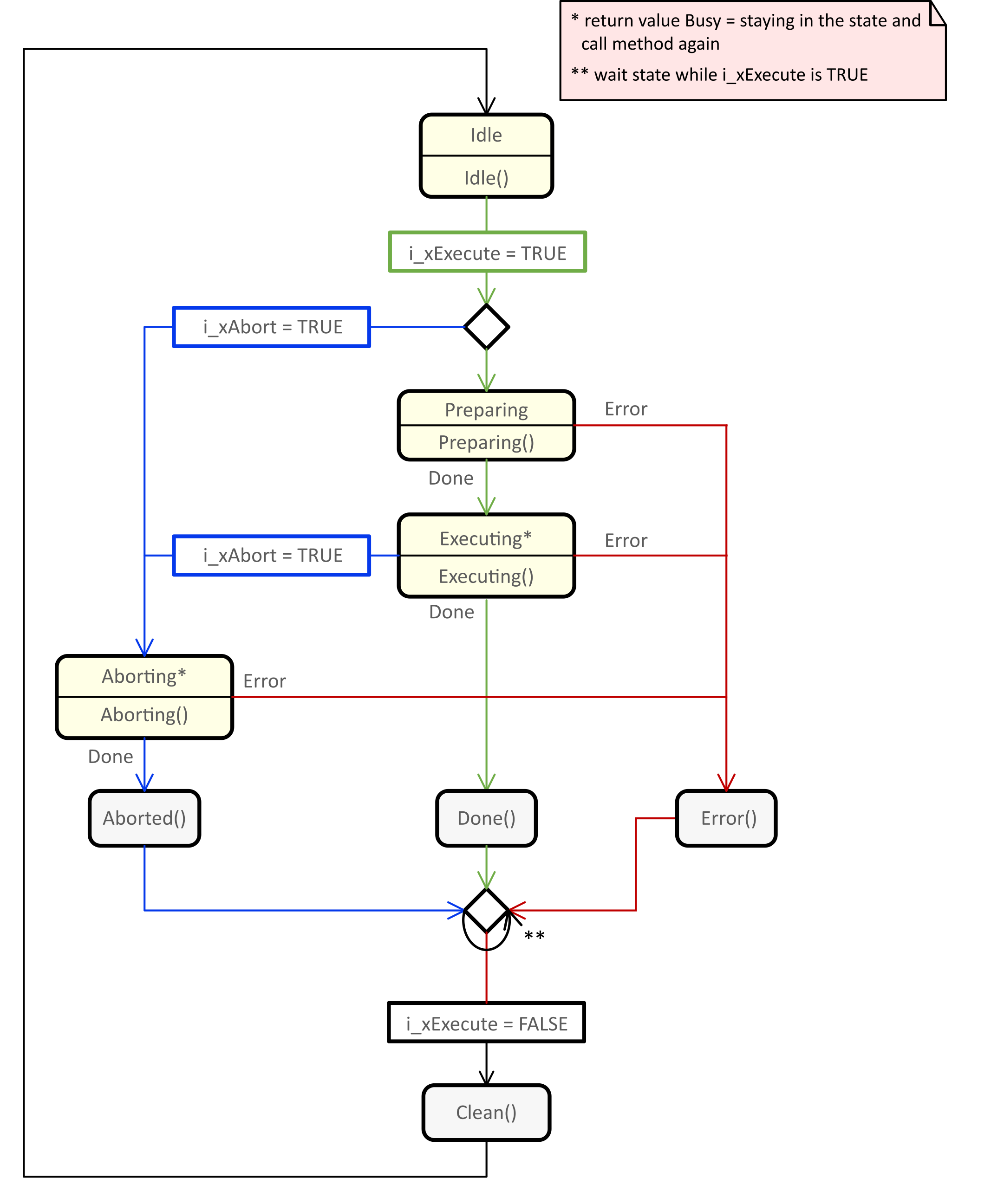
The state machine diagram illustrates the procedures, methods, states and state transitions that are defined for this function block.
-
For a legend describing the elements of the state machine diagram, refer to Legend of State Machine Diagrams.
-
For further information on the methods implemented, refer to the chapter Methods.
