Sercos III Interface
LED Indicators for the Sercos III Interface
The following figure presents the LED indicators for the Sercos III interface of the TM5CSLC100FS / TM5CSLC200FS and TM5CSLC300FS / TM5CSLC400FS:
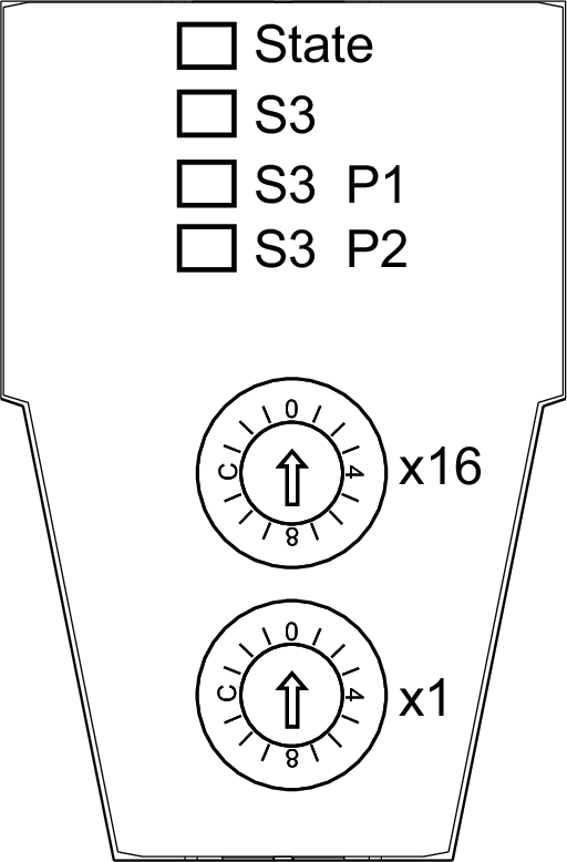
The following LED indicators are provided:
-
State
-
S3
-
S3 P1
-
S3 P2
State LED Indicator
The State LED is a green (status) / red (error) dual LED indicator:
The following table describes the State LED indicator:
|
LED color |
LED status |
State description |
|---|---|---|
|
- |
off |
No supply voltage applied or device is inoperable. |
|
green |
on |
No detected error, bus interface is initialized and ready for operation. |
|
green |
flashing (12.5 Hz) |
Initialization phase (booting of the I/O modules or setting up the I/O functional groups). |
|
green |
flashing (4 Hz) |
Recoverable error detected, such as missing I/O module (this LED indicator is reset when the error state is corrected). |
|
green |
flashing (0.66 Hz) |
New or modified configuration data (I/O modules or bus interface) have been received but not yet stored in the flash memory. |
|
red |
flashing (8 Hz) |
Unrecoverable error detected (for example, lack of resources, error detected in the firmware data flow). |
S3 (Sercos III) LED Indicator
The following table describes the S3 LED indicator:
|
LED color |
LED status |
State description |
Instructions |
|---|---|---|---|
|
- |
off |
Power is removed or there is no communication due to a connection interruption. |
Apply power or verify physical connections |
|
green |
on |
Active Sercos III connection without a detected error in the Communication Phase 4 (CP4). |
n.a. |
|
green |
flashing (4 Hz, 125 ms) |
The device is in Loopback mode. Loopback describes the situation in which the Sercos III telegrams have to be sent back on the same port on which they were received. Possible causes:
|
Close the ring. |
|
red |
on |
Sercos III diagnostic class error has been detected on port 1 and/or Sercos III communication is no longer possible on the ports (for example due to an encoder error). |
Reset condition
|
|
red/green |
flashing (4 Hz, 125 ms) |
Detected communication error. Possible causes:
|
Reset condition
|
|
orange |
on |
The device is in a communication phase CP0 up to and including CP3. Sercos III telegrams are received. |
n.a. |
|
orange |
flashing (4 Hz, 125 ms) |
Device identification |
Triggered by using the parameter |
|
(1) IdentifyDevice is a parameter in EcoStruxure Machine Expert. |
|||
S3 P1/S3 P2 LED Indicators
The following table describes the S3 P1 (Port 1) and S3 P2 (Port 2) LED indicators:
|
LED color |
LED status |
State description |
|---|---|---|
|
- |
off |
no cable connected |
|
green |
flashing |
active Sercos III communication |
|
green |
on |
link, but no telegrams / communication (for example controller is booting) |
Sercos Address
The Sercos address is set by two switches. Positioning the switches at 0 triggers the auto-addressing feature.
The following figure presents the Sercos address switches:
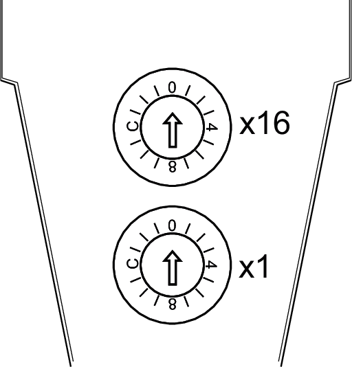
The following table describes the Sercos address, set with the 2 hexadecimal switches:
|
Sercos address |
Description |
|---|---|
|
0 dec (0 hex) |
Auto-addressing (not a valid address)
|
|
1-255 dec (1-FF hex) |
Manual addressing
|
|
(1) IdentificationMode is a parameter in EcoStruxure Machine Expert. |
|
Example:
In order to set the Sercos address 190 (dec) / BE (hex), set the two hexadecimal switches as follows:
-
Switch x1 = E
-
Switch x16 = B
Sercos III Ports
The following figure presents the RJ45 connectors of the Safety Logic Controller:
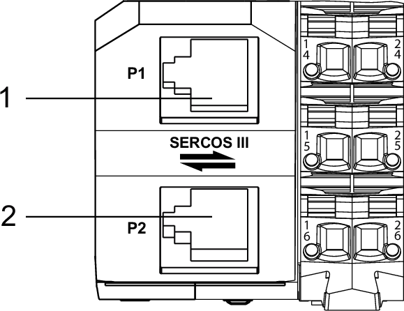
1 Sercos III PORT A (P1)
2 Sercos III PORT B (P2)
The following table lists the pin assignments for the RJ45 connectors:
|
Pin |
Assignment |
|---|---|
|
1 |
RXD (Receive Data) |
|
2 |
RXD\ |
|
3 |
TXD (Transmit Data) |
|
4 |
Termination |
|
5 |
Termination |
|
6 |
TXD\ |
|
7 |
Termination |
|
8 |
Termination |
For more information about the Sercos III ports, refer to Fieldbus Characteristics.