TM5STI4ATCFS Wiring
Pin Assignments / Connection Examples
The following channel pair applications are sufficient to achieve maximum PL e (EN ISO 13849-1:2008), maximum SIL 3 (EN IEC 62061:2010), maximum SIL 3 (EN IEC 61508:2010) and maximum SIL 3 (EN IEC 61511:2004).
|
TM5STI4ATCFS (with TM5ACTB5FFS) 2-wire connection, safety-related PT100/PT1000 input pair: 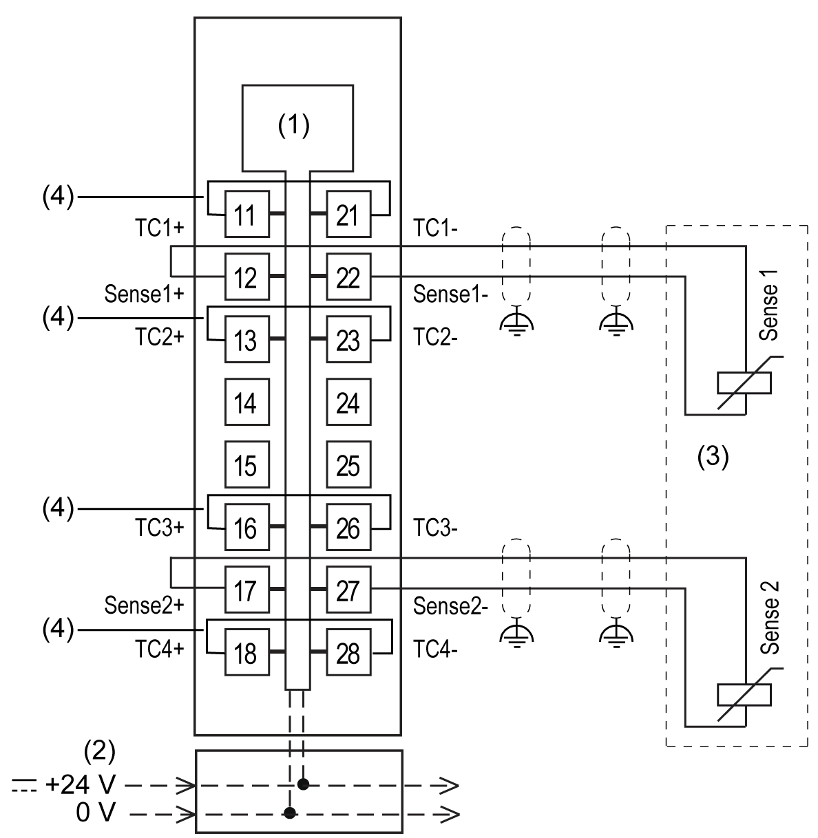
1 Internal electronics 2 24 Vdc I/O power segment integrated into the bus bases 3 2-channel PT100/PT1000 sensor 4 Jumper |
TM5STI4ATCFS (with TM5ACTB5EFS) Thermocouple input pair with terminal block for acquiring terminal temperature compensation: 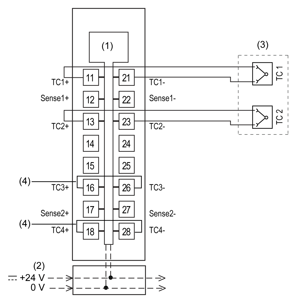
1 Internal electronics 2 24 Vdc I/O power segment integrated into the bus bases 3 2-channel thermocouple sensor 4 Jumper |
|
TM5STI4ATCFS (with TM5ACTB5FFS) Thermocouple input pair, remote terminal temperature compensation, PT100/PT1000 2-wire connection: 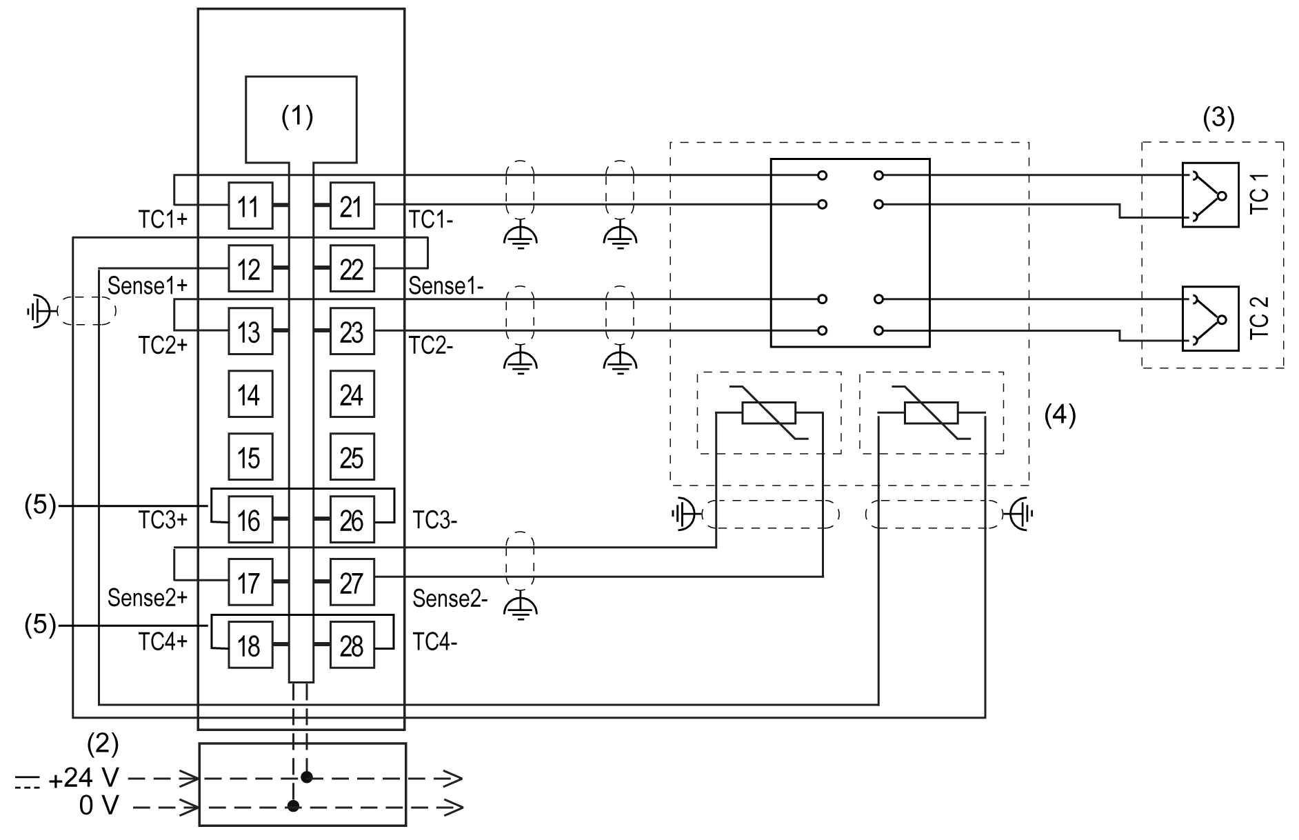
1 Internal electronics 2 24 Vdc I/O power segment integrated into the bus bases 3 2-channel thermocouple sensor 4 2-channel PT100/PT1000 sensor 5 Jumper |
|
Use shielded, properly grounded cables for all analog and high-speed inputs or outputs and communication connections. If you do not use shielded cable for these connections, electromagnetic interference can cause signal degradation. Degraded signals can cause the controller or attached modules and equipment to perform in an unintended manner.
| WARNING | |
|---|---|
1Multipoint grounding is permissible (and in some cases inevitable) if connections are made to an equipotential ground plane dimensioned to help avoid cable shield damage in the event of power system short-circuit currents.
| WARNING | |
|---|---|