Modbus TCP Cyclic Data Exchanges Configuration
Overview
To configure the Modbus TCP cyclic data exchanges, you have to:
-
Configure for each Modbus TCP slave devices the data exchanges request (on channels) and the I/O Mapping.
-
Configure the I/O scanner for Modbus TCP slave devices.
Modbus TCP Channel
A Modbus channel carries a Modbus request between the master and a slave.
For a generic slave device, you can use multiple channels. To send several different requests to a device, create several channels.
Configure the Modbus TCP Slave Device Channels
To configure the data exchanges (on channels) of a Modbus TCP slave device, proceed as follows:
|
Step |
Action |
|---|---|
|
1 |
In the , double-click a Modbus TCP slave device. Result: Its configuration window is displayed. |
|
2 |
Click the tab: 
|
|
3 |
To remove a non-predefined channel, select it and click . |
|
4 |
To change the parameters of a channel, select the channel and click .
NOTE: For the devices that provide predefined channels, only the value can be modified.
|
|
5 |
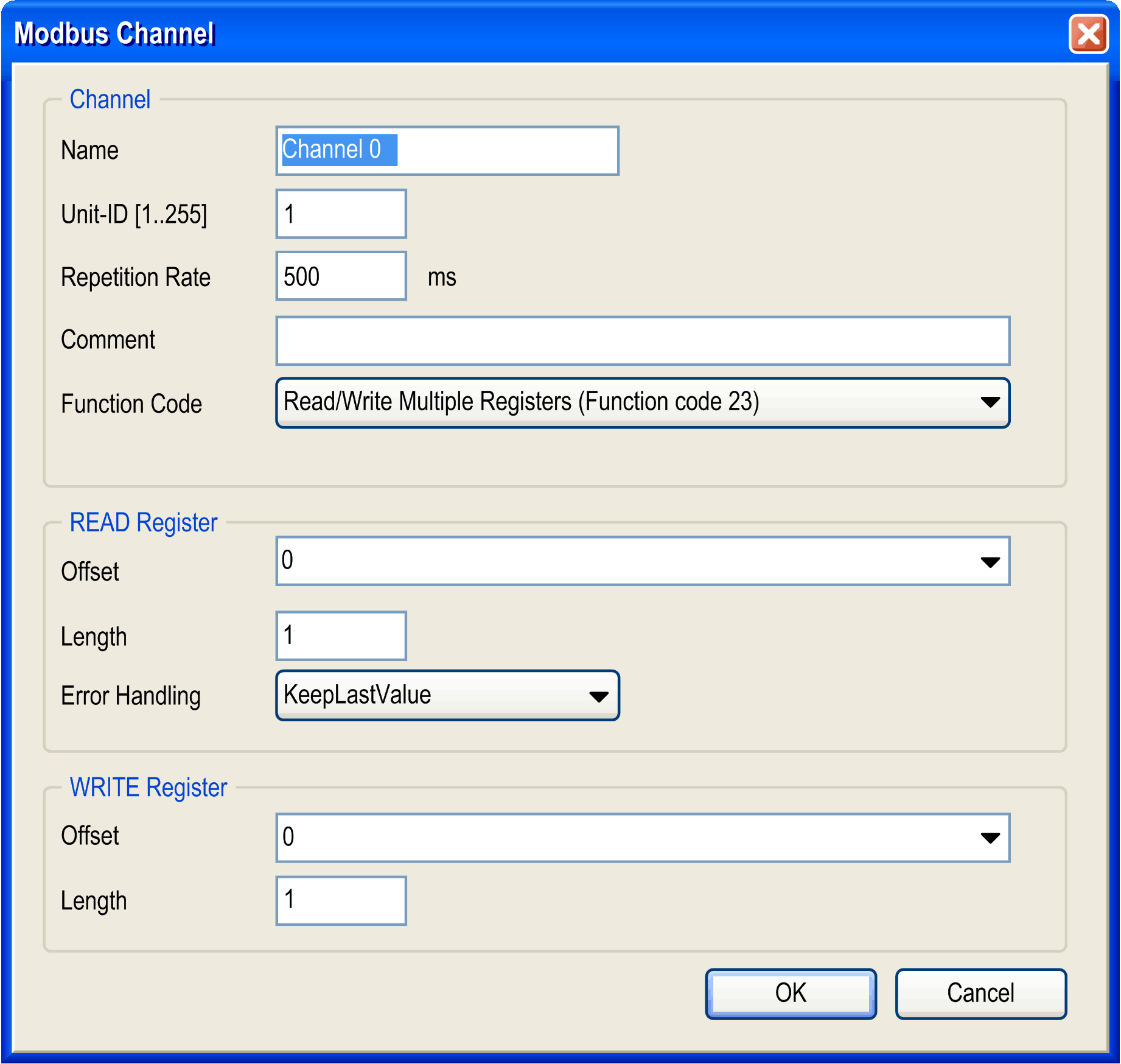
To add a channel, click . This dialog box is displayed: 
|
|
6 |
In the area, you can define:
In the area, you can define:
In the area, you can define:
|
|
7 |
Click to validate the configuration of the channel. Result: 
|
|
8 |
Repeat steps 5 to 7 to create other channels that define the Modbus communication with the device. For each Modbus request, you must create a channel. |
|
(1) Unit identifier is used with Modbus TCP devices which are composed of several Modbus devices, for example, on Modbus TCP to Modbus RTU gateways. In such case, the unit identifier allows reaching the slave address of the device behind the gateway. By default, Modbus/TCP-capable devices ignore the unit identifier parameter. |
|
Read/Write Register Length
The read/write register length depends on the Modbus function code.
This table contains, for 1 channel, the maximum length of the read/write registers:
|
Modbus function code |
Maximum length |
|
|---|---|---|
|
Read register |
Write register |
|
|
Read/write multiple registers (function code 23) |
125 |
121 |
|
Read registers (function code 03) |
125 |
- |
|
Write registers (function code 16) |
- |
123 |