Calibrating the Main Axes
Preparing the Robot Mechanics for a Calibration Movement
|
Step |
Action |
|---|---|
|
1 |
Remove the rotational axis (if present), the lower arms, and the parallel plate. For further information, refer to Replacing the Telescopic Axis, Replacing the Lower Arms, and Replacing the Parallel Plate. |
|
2 |
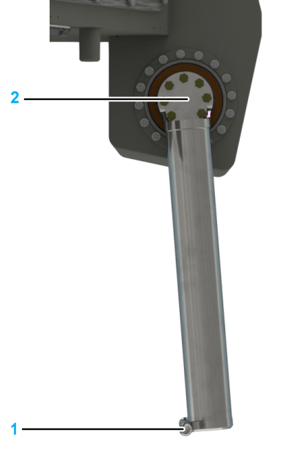
Do not move the upper arms beyond their vertical downward position (1) in order to prevent the individual robot arms from colliding with one another during their calibration travel (2). 
|
Sequence of the Calibration Process
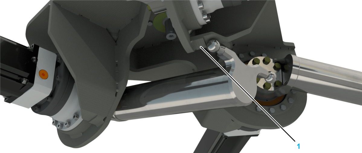
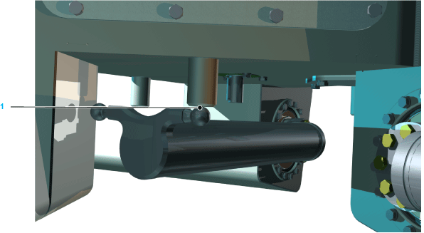
Calibrate each of the three main axis motors by using the function HomeOnTorque for moving the ball pin of the upper arm to the calibration bolts (1).
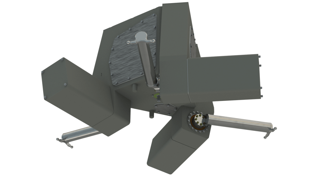
The following figure shows the upper arm of the robot VRKP1/VRKP2 at the calibration position:
The following figure shows the upper arm of the robot VRKP0/VRKP4/VRKP5/VRKP6 at the calibration position:
Verifying the Calibration
|
Step |
Action |
|---|---|
|
1 |
Move all three upper arms to the following angle in order to verify the calibration:
|
|
2 |
Measure whether the gap between the ball pins (1) of the individual upper arms is larger than 0.6 mm (0.236 in). 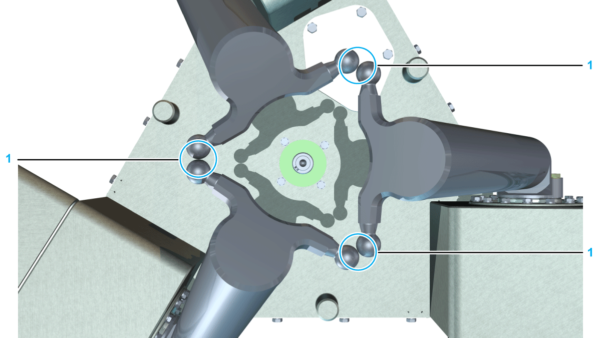
If the gap is larger than required or ball pins collide, proceed as follows:
|
|
3 |
Perform one of the following actions:
Result: The robot is now calibrated. |
|
4 |
Mount the lower arms, the parallel plate, and the telescopic axis if applicable. For further information, refer to Mounting the Lower Arms, Replacing The Parallel Plate, and Mounting the Telescopic Axis. |