Mounting the Payload to the Rotational Tilting Modules
Overview
Here you will find the following information:
Mounting the Gripper to the Rotational Tilting Module
|
Step |
Action |
|---|---|
|
1 |
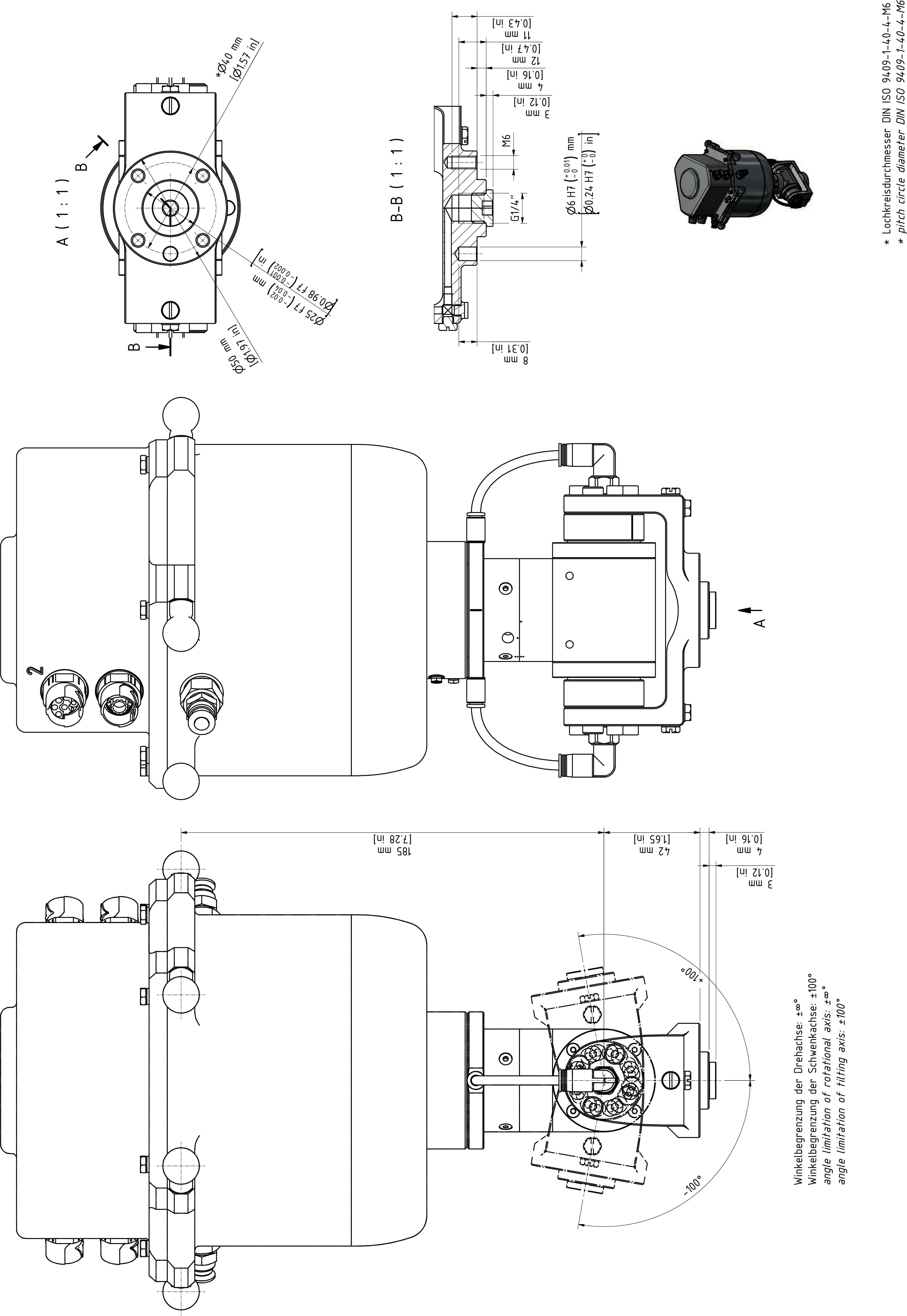
Fasten the gripper to the mounting points at the flange (1):
For further information, refer to Flange Dimensions for the Rotational Tilting Module. 
|
|
2 |
Calibrate the Rotational Tilting Module if this has not been done before mounting the gripper. For further information, refer to Calibrating the Double Rotational Module and the Rotational Tilting Module
NOTE:
|
Mounting the Gripper to the Rotational Tilting Module HD / HD-B
|
Step |
Action |
|---|---|
|
1 |
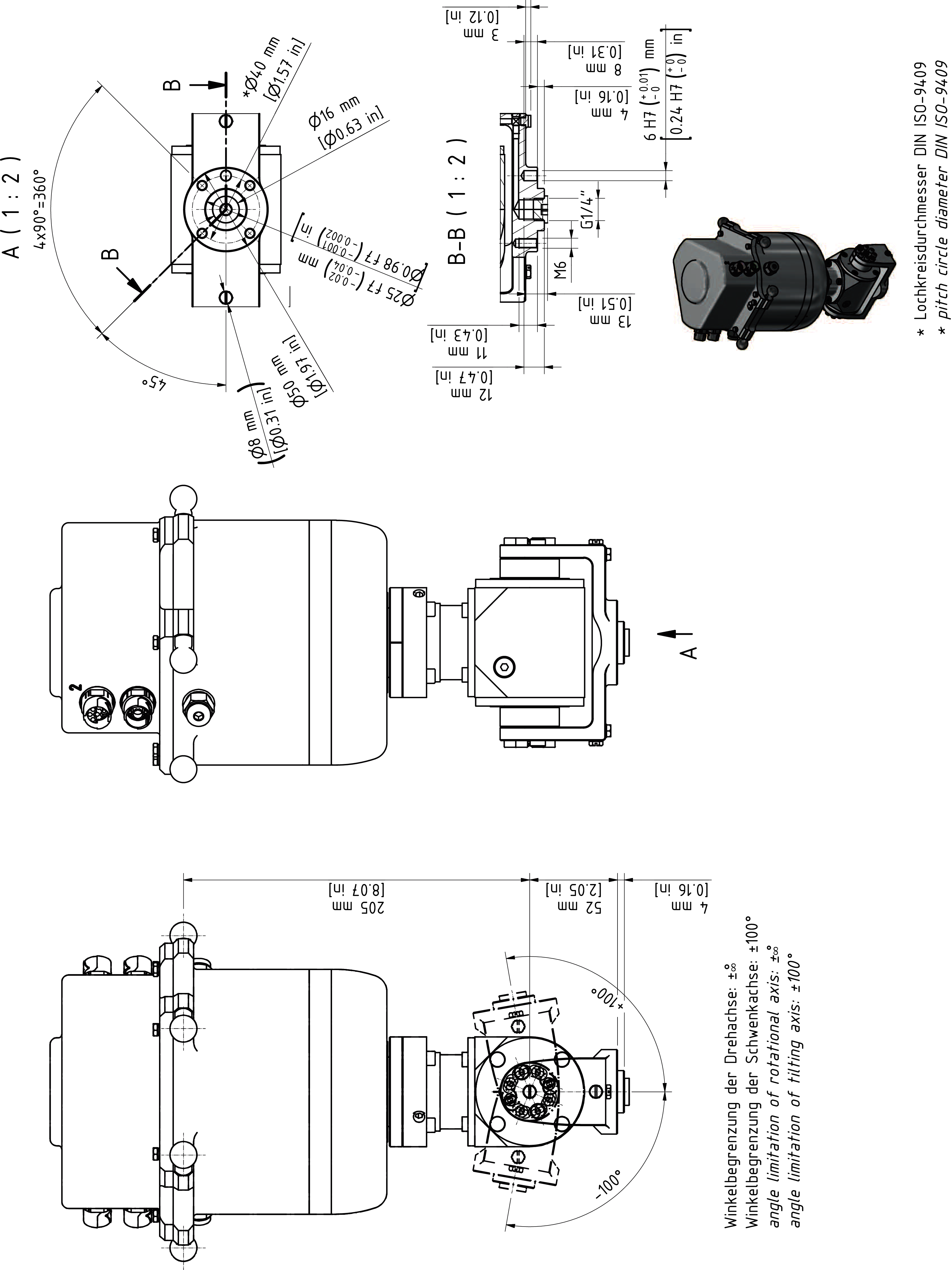
Fasten the gripper to the mounting points at the flange (1):
For further information, refer to Flange Dimensions for the Rotational Tilting Module HD. 
|
|
2 |
Calibrate the Rotational Tilting Module HD if this has not been done before mounting the gripper. For further information, refer to Calibrating the Double Rotational Module and the Rotational Tilting Module.
NOTE:
|
Supply of the Gripper on the Rotational Tilting Module
|
Step |
Action |
|---|---|
|
1 |
Connect the media line to one of the pneumatic plug-in connections (1.1 or 2.1) of the Double Rotational Module. The plug-in connection has a diameter of 6 mm (0.236 in). For further information, refer to Supply of the Gripper. |
|
2 |
When using a standard suction cup: Remove the plug screw (1.4) and mount the suction cup directly into the thread. Thread for suction cup: G1/4” x 12 mm (G1/4” x 0.47 in)
NOTE: Connection 1.1 is linked to connection 1.4
|
|
3 |
When using any of the other connections: Remove one of the plug screws of the associated connection (1.2, 1.3, 2.2, or 2.3) and mount your pneumatic connector. Thread size for the attachment: M5 x 4 mm (M5 x 0.157 in)
NOTE:
|