Mounting a Lexium™ MC12 Heavy-Duty Guide Rail
Overview
The following procedures describe the mounting of a Heavy-Duty guide rail.
Mounting a Heavy-Duty Guide Rail
The components of the Lexium™ MC12 multi carrier must be handled with care. Refer to Transport and Storage.
Heavy-Duty guide rails can bend if handled improperly and then may become unusable.
| NOTICE | |
|---|---|
|
Step |
Action |
|---|---|
|
1 |
When all the segments are in place (refer to Mounting the Lexium™ MC12 multi carrier Track), install the bottom Heavy-Duty guide rails, starting at an arc segment or at an open end of the track. The rails are mounted offset to the segments by design. |
|
2 |
Position a Heavy-Duty guide rail under the segments and loosely fasten the rail with M6x16 class 8.8 DIN 7984 screws.
NOTE: Make sure that the holes in the rails are aligned with the holes in the segments, and that the rails are aligned with the segment stops.
|
|
3 |
Loosely fasten the top rail screws at the first segment. |
|
4 |
Align the next rail. Make sure that the rails fit tightly together at the transition points. Use M5x8 (ISO 4026) set screws to fine-tune the rail alignment. Unscrew the set screws approximately halfway out of the rail to avoid contact with the support surface for the rails. To install the rails, slide a suitable mounting tool between the screws (in or across the rail direction) and carefully push them into place.
NOTE: Avoid scratching the surface of the rails.
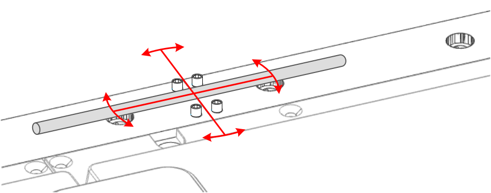
After aligning the rails, screw the set screws back into the rails. |
|
5 |
Tighten the screws of both bottom rails at the segment where the rails meet with a torque of 10.1 Nm (89.4 lbf-in). |
|
6 |
Proceed in the same way with the subsequent bottom rails until all bottom rails are installed. |
|
7 |
When all the bottom Heavy-Duty guide rails are installed, place the Heavy-Duty spacer on the track and align the holes with those in the segments. |
|
8 |
Locate the long holes of the Heavy-Duty guide rails and insert the cylindrical pins into the Heavy-Duty spacer. |
|
9 |
Beginning at an arc segment or an open end of the track, place the top Heavy-Duty guide rail over the segments with the Heavy-Duty spacer. The rails are mounted offset from the segments by design. The long holes must fit into the cylindrical pins. The holes in the rails must match the holes in the segments. Make sure that the Heavy-Duty spacer is aligned with the segment stop and that the Heavy-Duty guide rail is aligned with the cylindrical pins. |
|
10 |
Loosely attach the top rail with M6x35 class 8.8 DIN 7984 screws.
NOTE: The screws must go through the Heavy-Duty guide rails and the Heavy-Duty spacer.
|
|
11 |
Tighten the top rail screws at the first segment with a torque of 10.1 Nm (89.4 lbf-in). |
|
12 |
Mount Heavy-Duty carriers on the track (refer to Mounting a Lexium™ MC12 Heavy-Duty Carrier).
NOTE: Heavy-Duty carriers must be mounted before the rails are closed.
|
|
13 |
Align the next rail. Make sure that the rails fit closely together at the transition points. Use M5x8 (ISO 4026) set screws to fine-tune the rail alignment. Unscrew the set screws approximately halfway out of the rail to avoid contact with the support surface for the rails. To install the rails, slide a suitable mounting tool between the screws (in or across the rail direction) and carefully push them into place.
NOTE: Avoid scratching the surface of the rails.
After aligning the rails, screw the set screws back into the rails. |
|
14 |
Tighten the screws of both top rails at the segment where the rails meet with a torque of 10.1 Nm (89.4 lbf-in). |
|
15 |
Install each Heavy-Duty guide rail until all top rails are installed. |
|
16 |
After you install the rails, tighten the screws of the Lexium™ MC12 long stator motor segments with a torque of 10.1 Nm (89.4 lbf-in). Result: The Lexium™ MC12 multi carrier track is installed. |
|
17 |
Insert the Lexium™ MC communication interconnects from top between the segments. Attach the communication interconnect with its four M3x8 ISO 14583 screws with a torque of 0.6 Nm (5.31 lbf-in).
NOTE: If a communication interconnect is used to connect the system to the Sercos bus and/or a Safe Force Off (SFO) control device, refer to the Lexium™ MC communication interconnects.
|
|
18 |
Use the Lexium™ MC power cables, the Sercos cable, and the SFO cables to connect your Lexium™ MC12 multi carrier with the control cabinet. For details, refer to Electrical Installation. Result: The Lexium™ MC12 multi carrier track is installed and ready for verification. Refer to Verifying the Installation. |