Track Tab
Overview
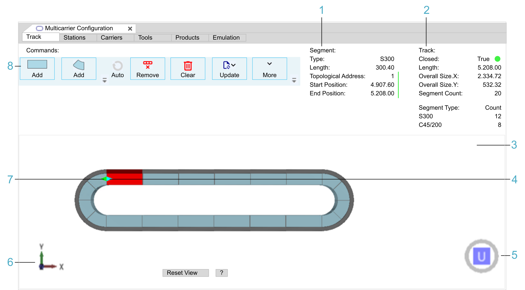
The Track tab allows you to create a track out of segments.
|
Legend item |
Description |
Refer to |
|---|---|---|
|
1 |
The Segment information provides information on the segment selected in the View area. |
|
|
2 |
The Track information provides information on the track. |
|
|
3 |
The View area displays the track with its components in a simplified 3-D graphical representation. |
|
|
4 |
The light blue arrow indicates the first segment connected to the Sercos infeed of the controller. |
|
|
5 |
The cube with U, D, B, F, R, or L is used for selecting a pre-defined view of the track. |
|
|
6 |
The 3-D coordinate system icon represents the 3-D coordinate system of the track. |
|
|
7 |
The green arrow indicates the first segment in working direction. |
|
|
8 |
The Commands area provides buttons to perform the following tasks:
|
Topological Direction versus Working Direction
As a basis for understanding the following explanations, note the general information on the topological and the working direction within the track:
-
Topological direction
The topological direction reflects the Sercos topology of the segments.
A light blue arrow marks the first segment (see legend item 4 in the figure). This segment must be connected to the Sercos infeed of the controller.
The topological addresses are assigned in the physical direction. The first segment is assigned the topological address 1, the second segment address 2, and so on.
-
Working direction
The default working direction is the same as the topological direction (not inverted). For further information on the working direction, refer to the EcoStruxure Machine Expert Multicarrier Library Guide.
A green arrow marks the first segment in working direction (see legend item 7 in the figure). The positions of carriers, tools and products are calculated relative to the first segment in working direction.
Commands
|
Command |
Description |
|---|---|
|
Add (straight / arc segment) |
Adds a segment after the selected segment in the topological direction. The first segment you add is interpreted as the topological start of your track.
NOTE: You must physically connect the Sercos bus to this segment.
The topological start of your track is represented by a light blue arrow. |
|
Auto |
Completes the track automatically. This button becomes active as soon as the track can be closed by a point symmetric copy of the already configured track. |
|
Remove |
Removes the segment selected in the View area. You can also select multiple segments by holding the Ctrl key while selecting the segments. |
|
Clear |
Removes all segments. |
|
Update |
Provides different possibilities to synchronize the editor with the code and the devices in your project in case the are not activated as described in Automatic Updates (Project Settings). For a description of these Update commands to perform manual updates, refer to Update Command (Details). |
|
More |
Provides commands for export / import and the possibility to display the track options:
|
|
Direction: |
Only displayed when the option Show Track Options is enabled from the list of More commands.
Also refer to Topological Direction versus Working Direction. |
|
Count: |
Only displayed when the option Show Track Options is enabled from the list of More commands. Enter the number of segments to be created in the Count field and click the Add button (straight / arc segment). Result: The segments are displayed in the View area. |
Automatic Updates (Project Settings)
If you activate the option in the tab, the content of the multi carrier configuration is automatically synchronized with the Devices tree and the generated code.
-
If you make modifications in the editor, these modifications are automatically updated (Update ) when another editor within EcoStruxure Machine Expert becomes the active window.
-
If you make modifications to a multi carrier device or to the GVL_MulticarrierConfiguration, these changes are automatically updated (update ) to the editor when the editor becomes the active window.
| NOTICE | |
|---|---|
Update Command (Details)
If you do not activate the option in the tab, the following update commands can be used to manually adapt devices in the Devices tree and multi carrier objects in the Applications tree to the content of the editor and vice versa.
-
To Devices
-
For the track you created in the Track tab, a device is inserted under the Sercos Master device in the Devices tree.
-
For the segments of your track, devices are inserted under the device.
-
For the carriers, a device is inserted under the PacDrive LMC device in the Devices tree.
The device contains the devices.
If the aforementioned devices already exist in the Devices tree, they will be adapted to the content of the editor.
The names that are assigned to the newly created devices in the Devices tree are configured in the dialog box (refer to Project Settings - Multicarrier Configuration Editor.
-
-
To Code
For the track you created in the Track tab, a MulticarrierConfiguration folder is inserted under the Application node in the Applications tree.
This folder contains the GVL_MulticarrierConfiguration and the associated structures (for example, ST_Carrier, ST_Segment, ST_Station, ST_ToolType).
If code already exists in the Applications tree, it will be adapted to the content of the editor.
The name that is assigned to the newly created folder in the Devices tree is configured in the dialog box (refer to Project Settings - Multicarrier Configuration Editor.
If you activate the option in the tab, the To Code operation also creates the emulation data that is needed for emulating the track with the .
Emulation data comprises:-
A MulticarrierEmulation folder which is inserted under the Application node in the Applications tree. This folder contains the GVL_MulticarrierEmulation and the SR_EmulationInterface program.
-
The SR_EmulationInterface program which synchronizes the OPC UA structures with the GVL_MulticarrierEmulation. Do not change the content of this program.
The GVL_MulticarrierEmulation must be set by your application so that the can emulate the track. For further information, refer to the EcoStruxure Machine Expert DigitalTwinCommunication Library Guide.
-
-
To All
Synchronizes both the code and the devices in your project with the editor.
-
From Devices
You can modify your multi carrier configuration by adding/changing/deleting segments or carriers. To apply the modifications to the editor, execute the From Device command. Your configuration in the editor is then updated from the configuration in the Devices tree.
-
From Code
You can add/change/remove your multi carrier definition in the code, like adding stations, carriers or segments by editing the GVL_MulticarrierEmulation. To apply the modifications to the editor, you can read from code by executing the From Code command. The configuration in the editor is updated according to your definition in the code.
-
From Last Modified
With From Last Modified, you synchronize the track in the editor with the Devices tree or with the GVL depending on what was last modified.
Segment Information
|
Information |
Description |
|---|---|
|
Type |
Segment type. For example: S300 (straight, 300 mm), C45/200 (45° arc, 200 mm) |
|
Length |
Segment length. For example: 300.4 [mm], 200.4 [mm] |
|
Topological Address |
Topological address of the segment. The Sercos bus must be physically connected to the segment with the topological address 1. Also refer to Topological Direction versus Working Direction. |
|
Start Position |
Start position of the segment [mm] in working direction. Also refer to Topological Direction versus Working Direction. |
|
End Position |
End position of the segment [mm] in working direction. |
Track Information
|
Information |
Description |
|---|---|
|
Closed |
True = Closed track False = Open track |
|
Length |
Track length. For example: 3405.60 [mm] |
|
Overall Size, X |
Overall size of the track in X direction |
|
Overall Size, Y |
Overall size of the track in Y direction |
|
Segment Count |
Total number of segments that constitute the track. |
|
Segment Type Count |
Number of straight and arc segments that constitute the track. |
View
The View area displays the track with its components in a simplified 3-D graphical representation.
|
Element |
Description |
|---|---|
|
3-D coordinate system icon |
Represents the 3-D coordinate system of the track (see legend item 6 in the figure). |
|
Cube U, D, B, F, R, L |
Serves to select a pre-defined view of the track (see legend item 5 in the figure). If the view of the track is rotated, click one of the cube sides to display the track in a pre-defined view:
Double-click a side of the cube to display the opposite view of the track. For example, double-clicking the U (Up view) displays the D (Down view). You can also use the keyboard. Click Shift+Ctrl+U (D, B, F, R, L). |
|
Show Stations |
Switches between showing and not showing the stations. The track stations are created in the Stations tab. |
|
Reset View |
Displays the track in the up view. The complete track is centered in the View area. |
|
? |
Displays a help text for zooming, rotating, and moving the track in the View area. Click ? again to hide the help text. |
Zooming, rotating, and moving the track in the View area:
-
Zooming:
-
Use the Page Up / Page Down keys of the keyboard.
-
Use the scroll wheel of the mouse.
-
Hold down the Ctrl key, hold down the right mouse button, and move the mouse.
-
-
Rotating:
-
Use the arrow keys of the keyboard.
-
Hold down the right mouse button, and move the mouse.
-
-
Moving:
-
Hold down the Shift key, and use the arrow keys of the keyboard.
-
Hold down the Shift key, hold down the right mouse button, and move the mouse.
-
Hold down the scroll wheel of the mouse, and move the mouse.
-