Load Case Rack and Pinion Drive
Overview
The load case allows you to design applications for a driven pinion that changes the rotary motion into linear motion of the rack.
Parameters
The load case allows you to specify the parameters described in the table:
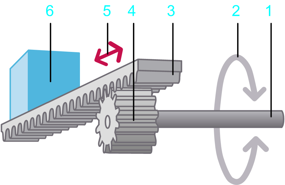
1 Input shaft
2 Rotary motion at the input shaft
3 Rack
4 Pinion
5 Linear movement of the load described by the motion profile
6 Load
|
Parameter |
Description |
Physical Quantity |
|---|---|---|
|
|
The distance between two teeth on the rack. The tooth pitch together with the number of teeth on the pinion determines the transmission ratio between the linear movement of the load and the rotary movement of the input shaft. |
Length |
|
|
The number of teeth on the pinion which drive the rack. |
– |
|
|
The diameter of the pitch circle. |
Length |
|
|
Mass of the moved load (without the mass of the rack). |
Mass |
|
|
Mass of the rack. |
Mass |
|
|
Moment of inertia of the pinion (without the inertia of the load and the rack). |
Moment of inertia |
|
|
A torque that applies to the input shaft. This parameter can have a positive value, or 0. During movement (when velocity is different from 0) this torque acts opposed to the direction of the motion. The absolute value of the torque during movement is constant, independent of the velocity. At stand-still (velocity =0), this torque does not occur. A typical example for this type of torque is kinetic friction between solid bodies. 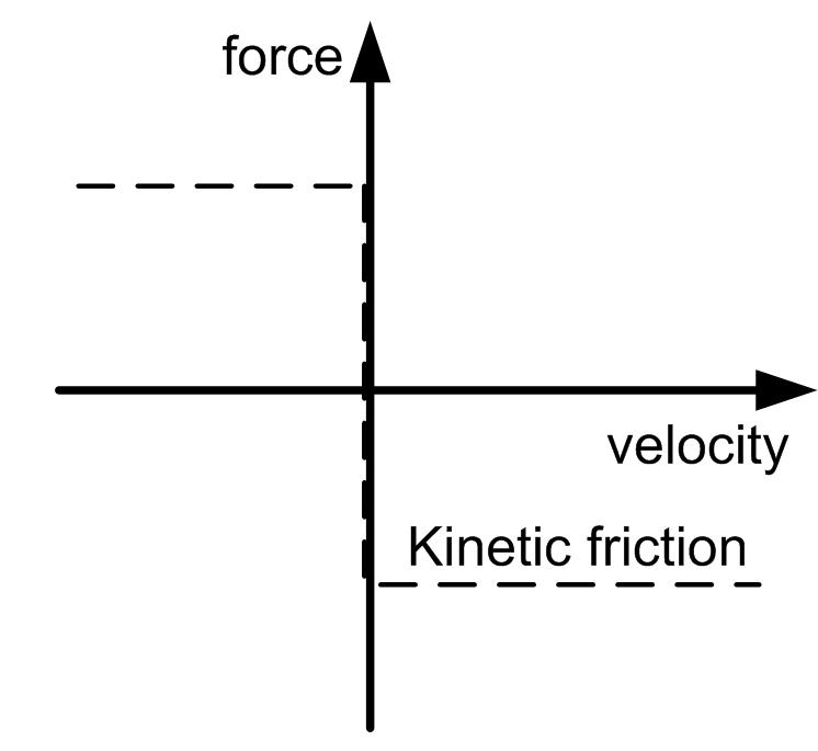
|
Force |
|
|
Static additional force at the input shaft. A positive value or negative value, or 0, is allowed. A positive value indicates that the force applies in positive direction of the load. A negative value indicates that the force applies in negative direction of the load. The absolute value and the direction of the force are constant and apply during motion and standstill. They are independent of the velocity. An additional constant force is caused, for example, by a suspended load. 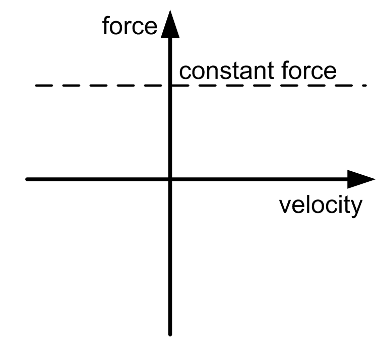
|
Force |
|
|
Velocity-dependent additional force at the input shaft. This parameter can have a positive value, or 0. The absolute value of the force is proportional to the absolute value of the velocity. The direction of the force is opposed to the direction of motion. A viscous friction force is caused by the friction of a fluid. 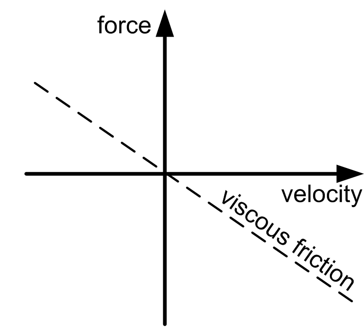
|
Force per velocity |
|
|
Inclination angle of the rack in degrees (–90°...+90°). With a positive value, the rack is inclined in upward direction, meaning in opposite direction to the force of gravity. This increases the force required to move the load. With a negative value, the rack is inclined in downward direction. This reduces the force required to move to load. |
Angle |
|
|
The motion profile that is used a a basis for calculations for this axis. The motion profile of the load case describes a linear movement of the load (legend item 6 in the graphic above the table). |
Linear motion |
|
|
The load profile that is used in combination with another motion diagram to define an additional load. It allows you to define a load that is exerted on a servo axis during specific sequences of motion. |
Force |