Linear Moving Coordinate System
Overview
If the target coordinate system is a linear moving system, the samples required to estimate the orientation can be acquired using reference objects placed on the system to teach.
-
Overall, it is important to select a reference object that ensures good repeatability of the sampling.
-
The execution of this procedure using the reference grid only requires the grid points inside one set (for example, Set 1).
Procedure Using two Reference Targets on a Conveyor Belt
|
Step |
Action |
|---|---|
|
1 |
Start by printing the provided teaching grid. In this example the Reference Grid. Only Set 1 of the grid is used during the procedure. |
|
2 |
Place the printed teaching grid on the physical coordinate system to teach. Align the X and Y axis of the teaching grid to the equivalent axes of the coordinate system to teach. Compared to the fixed coordinate system, the presence of misalignments do not influence the estimated orientation.
NOTE: It is essential that the teaching grid does not move with respect to the surface of the other system.
|
|
3 |
Define an instance of the teaching function block: |
|
4 |
Call the method SetNumberOfSamplesPerSet to set the number of samples that are stored for each set. In this case, the samples of Set 1 is acquired at different conveyor belt positions, meaning that multiple sets are acquired having two samples each. The called method provides a value of 2 as input: |
|
5 (Optional) |
The teaching requires touching points with the robot on the surface of the other system to teach. This procedure is performed with a tool mounted on the robot. The cartesian pose transformation introduced by a tool can be described with ROB.IF_RobotConfiguration.ConfigureTool. Then the tool can be selected with the method ROB.IF_RobotMotion.SetTool. Once a tool is set, the feedback ROB.IF_RobotFeedback.rstRefPositionTCP accounts for that. If a rotation of the tool could influence the TCP position, the orientation must be considered, and it is then required to configure the robot so that the orientation is properly handled (see also ROB.IF_RobotConfiguration.MapComponentToDrive). |
|
6 |
Move the robot to a position where it is aligned to the circle marked with the number 1 inside Set 1, as displayed in the graphic.
NOTE: The angle α marked in the image represents a misalignment between the orientation of the coordinate system to teach and the teaching grid print.
|
|
7 |
Call the method AddSample to store the position of the TCP: Where the variable stCurrentTCPPosition is of type SE_MATH.ST_Vector3D and its value can be obtained for example from the property ROB.IF_RobotFeedback.rstRefPositionTCP.
NOTE: After calling AddSample a first time for the selected set, the value of udiNumberOfSamplesInActiveSet increases by one.
|
|
8 |
Move the robot to a position where it is aligned to the circle marked with the number 2 inside Set 1, as displayed in the graphic. 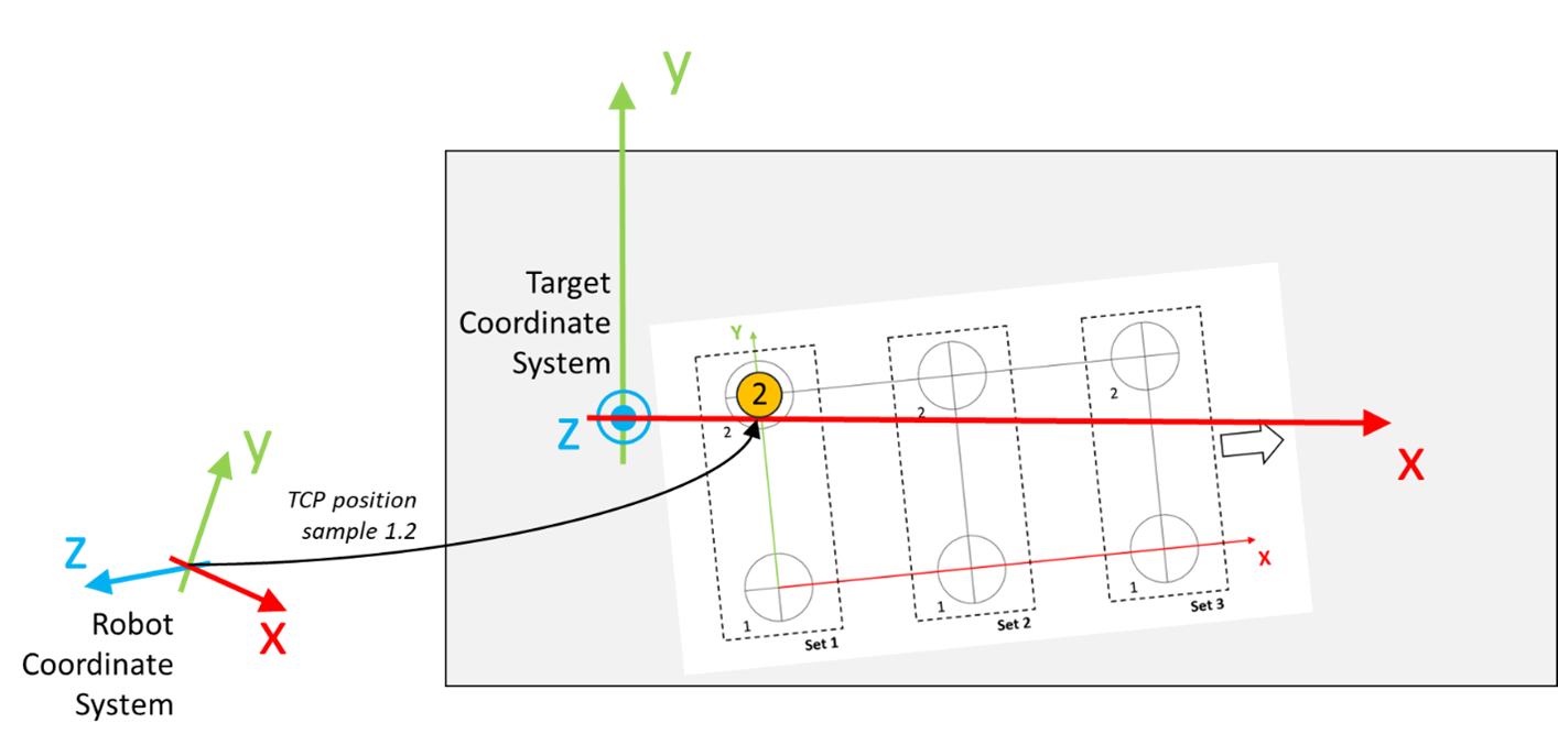
|
|
9 |
Call the method AddSample to store the position of the TCP:
NOTE: After calling AddSample a second time for the selected set, the set is completed and the value of udiNumberOfCompleteSets increases by one.
|
|
10 |
Perform a forward motion of the conveyor belt. The length of the motion must be greater than or equal to the distance between the point 1 and 2 of the set. 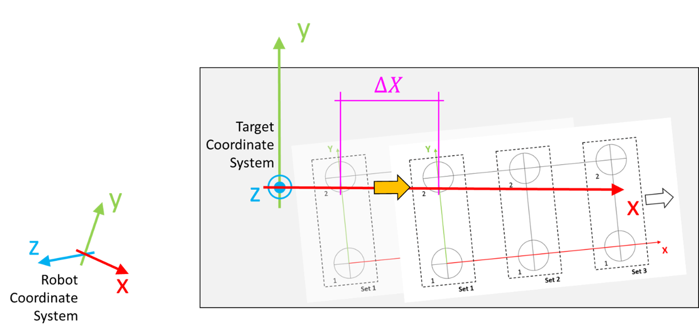
NOTE: The distance ∆X marked in the image represents the distance of the relative positioning.
|
|
11 |
Move the robot to a position where it is aligned to the circle marked with the number 1 inside Set 1, as displayed in the graphic. In this case the sampling is performed on the set marked as Set 1 on the teaching grid that is moved to a different position once a set is completed. 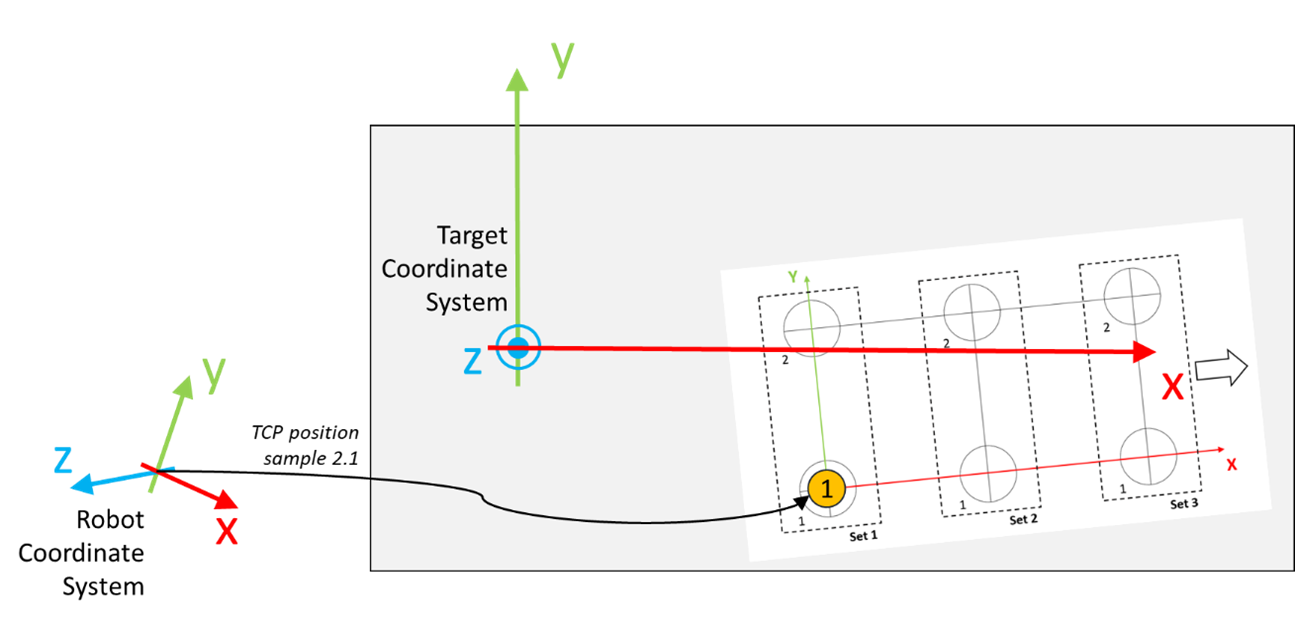
|
|
12 |
Call the method AddSample to store the position of the TCP: |
|
13 |
Move the robot to a position where it is aligned to the circle marked with the number 2 inside Set 1, as displayed in the graphic. 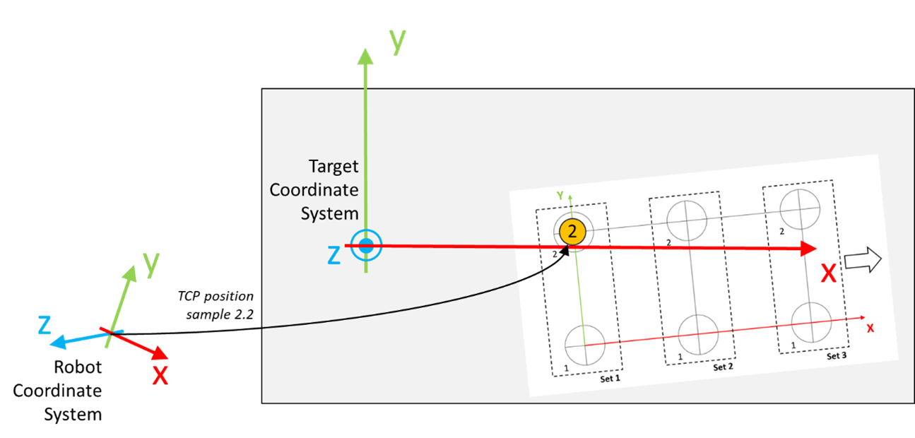
|
|
14 |
Call the method AddSample to store the position of the TCP: |
|
15 |
Perform a forward motion of the conveyor belt. The length of the motion must be greater than or equal to the distance between the point 1 and 2 of the set. 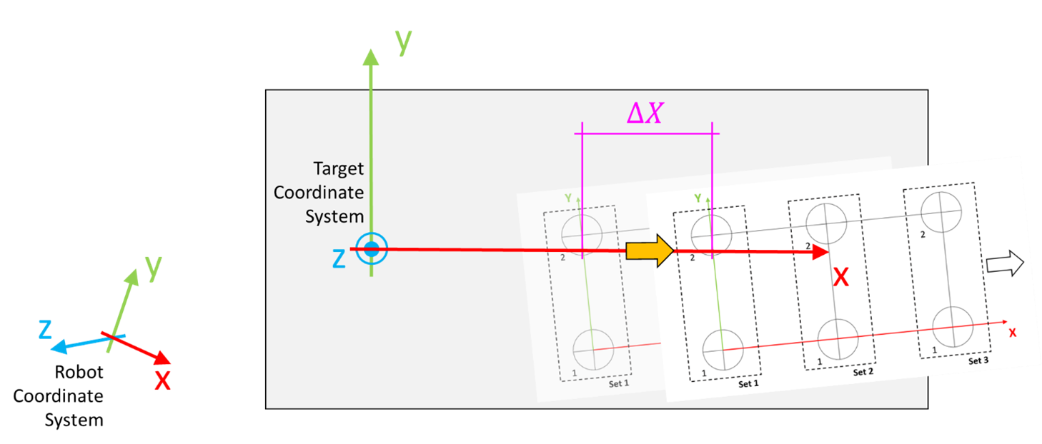
NOTE: The distance ∆X marked in the image represents the length of the relative positioning. The length of the relative positioning between the acquisition of two sets may differ.
|
|
16 |
Move the robot to a position where it is aligned to the circle marked with the number 1 inside Set 1, as displayed in the graphic. 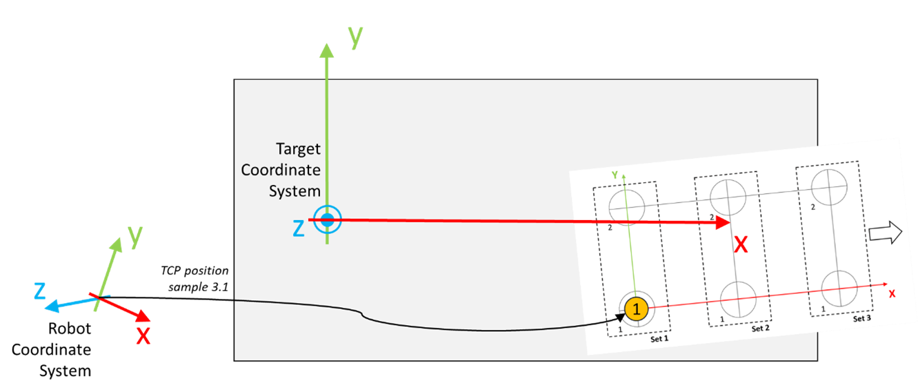
|
|
17 |
Call the method AddSample to store the position of the TCP: |
|
18 |
Move the robot to a position where it is aligned to the circle marked with the number 2 inside Set 1, as displayed in the graphic. 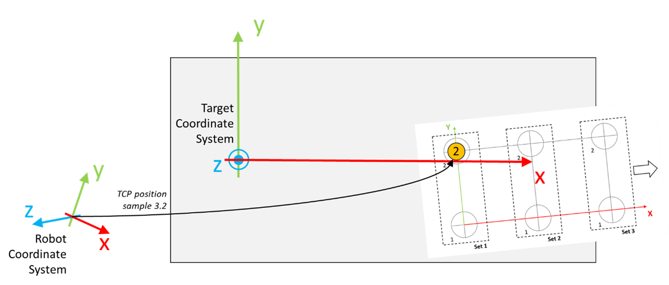
|
|
19 |
Call the method AddSample to store the position of the TCP: |
|
20 |
Call the method EstimateOrientation to estimate the orientation of the target coordinate system based on the acquired sets of samples:
NOTE:
|