Operation Mode
Overview
Refer to the Smart Template Modules User Guide for more information on displaying the different tabs.
The tab provides a tab for each operation mode on the left-hand side:
On the right-hand side, the tab displays a visualization of the robot. The visualization can be configured ( and ).
Manual Tab
-
The left-hand side of the tab helps you to move the robot manually.
-
The right-hand side of the tab displays the robot movements. The visualization can be configured ( and ).
| WARNING | |
|---|---|
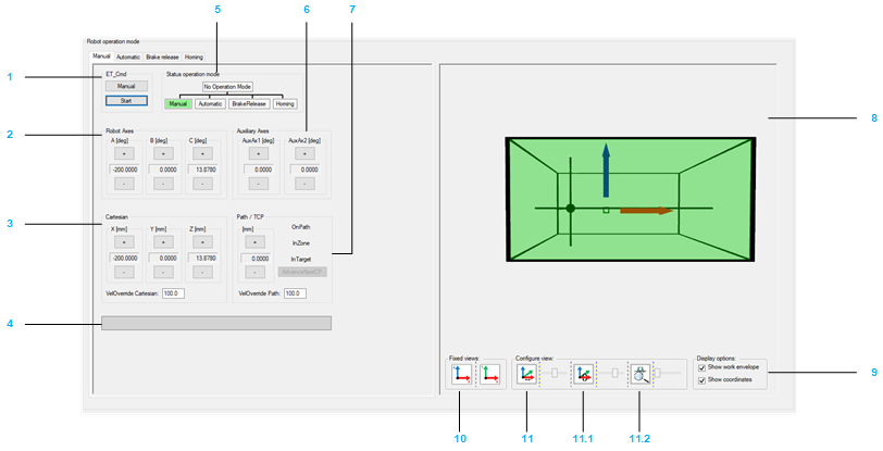
Moving the robot manually:
|
Item |
Description |
|---|---|
|
1 |
If the module is not in the operation mode , click the button to send the command RM.ET_Cmd.Manual, and then click the button to send the command RM.ET_Cmd.Start.
NOTE: Alternatively you can send the commands via the ModuleInterface (for example, iq_etCmd).
The displayed Cartesian parameters depend on the configuration of (refer to Robotic Library Guide). If the operation mode is accepted, the background color of the operation mode status switches to green. |
|
2 |
Click the buttons (positive / negative) to move (jog) along the robot axes by controlling the corresponding drives. |
|
3 |
Click the buttons (positive / negative) to move (jog) the TCP (Tool Center Point) along the axes of the Cartesian coordinate system. The displayed Cartesian parameters depend on the configuration of ET_WorkingPlane (refer to Robotic Library Guide). : Proportional influence of the active Cartesian jogging velocity. Unit: % |
|
4 |
Displays the pending hardware and software limits. |
|
5 |
Displays the operation mode of the module. If the robot is in operation mode, you can move the robot step-by-step with the buttons of the various jogging modes:
|
|
6 |
Click the buttons (positive / negative) to move (jog) the Auxiliary Axes.
NOTE: The buttons are only displayed if Auxiliary Axes have been configured.
|
|
7 |
Click the buttons (positive / negative) to move (jog) the TCP (Tool Center Point) along a connected path (if a connected path is available). For status information on the TCP movement, refer to the feedback properties xOnPath, xInZone, and xInTarget (refer to Robotic Library Guide). : Proportional influence of the active path jogging velocity. Unit: %. |
Configuring the visualization:
|
Item |
Description |
|---|---|
|
8 |
Shows the movement of the robot, particularly the TCP (Tool Center Point) movement within the working plane. |
|
9 |
Activate the check boxes to define what is displayed in the (work envelope, coordinate system). |
|
10 |
Click one of the buttons to select a fixed default view of the robot. |
|
11 |
Move the sliders to configure the rotation, translation, and zoom of the displayed robot. 11.0 Rotation around X-axis 11.1 Translation in direction of X-axis 11.2 Zoom |
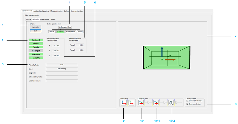
Automatic Tab
-
The left-hand side of the tab provides feedback and diagnostic information on the robot.
-
The right-hand side of the tab displays the robot movements. The visualization can be configured (refer to above).
|
Item |
Description |
|---|---|
|
1 |
If the module is not in the operation mode , click the button to send the command RM.ET_Cmd.Auto, and then click the button to send the command RM.ET_Cmd.Start.
NOTE: Alternatively you can send the commands via the ModuleInterface (for example, iq_etCmd).
If the operation mode is accepted, the background color of the operation mode status switches to green. |
|
2 |
|
|
3 |
Diagnostics of the robot module. Detailed information can be found under: ET_DiagExt in RoboticModule Library Guide. |
|
4 |
Displays the operation mode of the module. |
|
5 |
AuxAxes will only be displayed if Auxiliary Axes have been configured. Detailed information can be found under: IF_RobotFeedback.ralrRefPositionAuxAx in Robotic Library Guide. |
|
6 |
Detailed information can be found under: IF_RobotFeedback.rstRefPositionTCP in Robotic Library Guide. |
Configuring the visualization:
|
Item |
Description |
|---|---|
|
7 |
Shows the movement of the robot, particularly the TCP (Tool Center Point) movement within the working plane. |
|
8 |
Activate the check boxes to define what is displayed in the (work envelope, coordinate system). |
|
9 |
Click one of the buttons to select a fixed default view of the robot. |
|
10 |
Move the sliders to configure the rotation, translation, and zoom of the displayed robot. 10.0 Rotation around X-axis 10.1 Translation in direction of X-axis 10.2 Zoom |
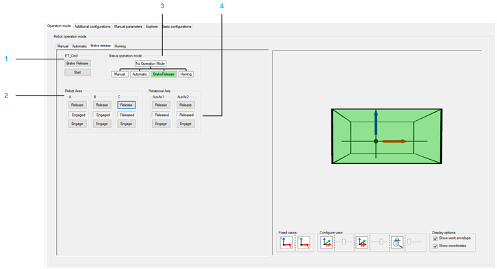
Brake Release Tab
-
The left-hand side of the tab helps you to release/engage the brake(s) of one or several robot axes.
-
The right-hand side of the tab displays the robot movements. The visualization can be configured (refer to above).
|
Item |
Description |
|---|---|
|
1 |
If the module is not in the operation mode , click the button to send the command RM.ET_Cmd.BrakeRelease, and then click the button to send the command RM.ET_Cmd.Start.
NOTE: Alternatively you can send the commands via the ModuleInterface (for example, iq_etCmd).
If the operation mode is accepted, the background color of the operation mode status switches to green. |
|
2 |
The indicator between the and the button displays the state of the respective brake. |
|
3 |
Displays the operation mode of the module. |
|
4 |
The indicator between the Release and the Engage button displays the state of the respective brake. |
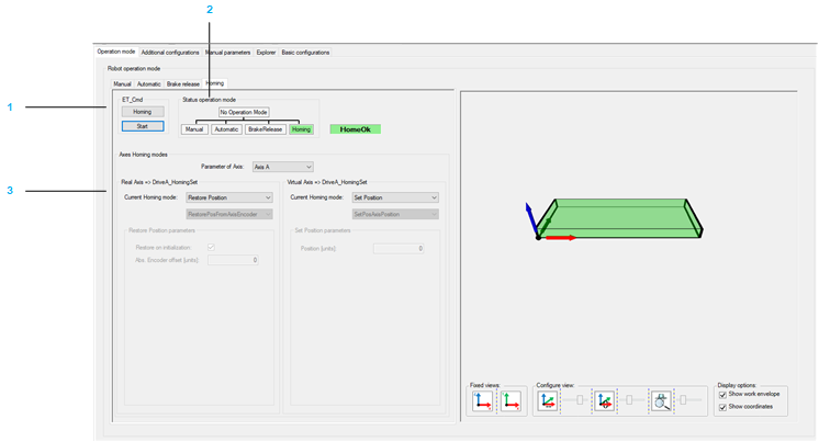
Homing Tab
The tab displays the homing mode of the robot axes.
|
Item |
Description |
|---|---|
|
1 |
If the module is not in the operation mode , click the button to send the command RM.ET_Cmd.Homing, and then click the button to send the command RM.ET_Cmd.Start.
NOTE: Alternatively you can send the commands via the ModuleInterface (for example, iq_etCmd).
If the operation mode is accepted, the background color of the operation mode status switches to green. |
|
2 |
Displays the operation mode of the module. |
|
3 |
Displays the configured homing mode of the respective axis in case of working mode and working mode .
NOTE: All of the Cartesian Robot are supported within the Robotic Module library.
|
Homing modes:
|
Mode |
Description |
|---|---|
|
Touchprobe |
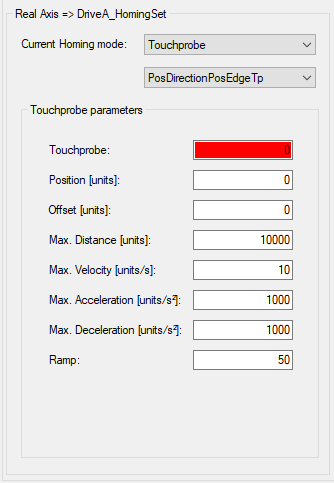
For detailed information about the parameters refer to PDL.ST_HomeTp. You can also find a list of possible Touchprobe modes in PDL.ET_HomeTpMode. Ensure to select the right Touchprobe signal.
NOTE: Due to controller dependent Touchprobe configuration (LMC Pro and Pro2, for example TP_0; LMC Eco, for example ADI_1), a message that the default value 0 must be configured to a valid value is displayed.
|
|
Input / Sensor |
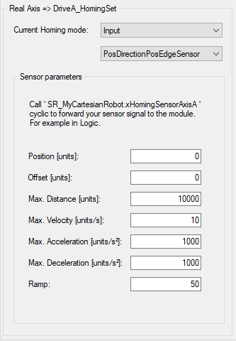
For detailed information about the parameters refer to PDL.ST_HomeIn. You can also find a list of possible Input/Sensor modes in the PDL.ET_HomeInMode. Use the property SR_<CartesianRobotName>.xHomingSensor<A | B | C | ..>. (See chapter Explorer) to set the sensor value. |
|
Limit Switch |
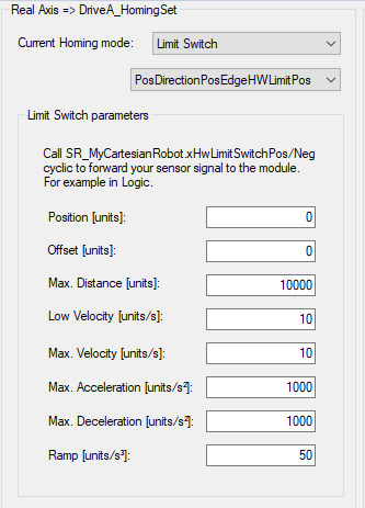
For detailed information about the parameters refer to PDL.ST_HomeLimitSwitch. You can also find a list of possible Limit Switch modes in the PDL.ET_HomeLimitSwitchMode To set the signal of the hardware Limit Switch you have to set the corresponding value in the (for example iq_stRoboticModuleItf.iq_ifHardwareLimit.raxAxisNegative). |
|
Torque |
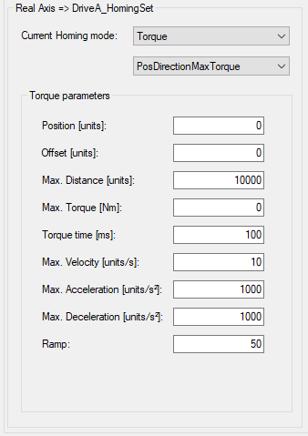
For detailed information about the parameters refer to PDL.ST_HomeTorque. You can also find a list of possible Torque modes in the PDL.ET_HomeTorqueMode. |
|
Move on Position |
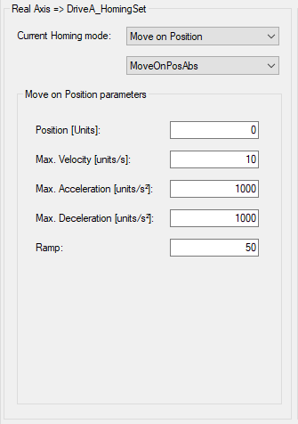
For detailed information about the parameters refer to PDL.ST_HomeMoveOnPos. |
|
Set Position |
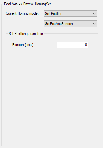
For detailed information about the parameters refer to PDL.ST_HomeSetPos. You can also find a list of possible Torque modes in the PDL.ET_HomeSetPosMode. |
|
Restore |
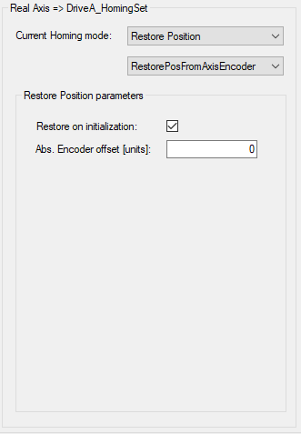
For detailed information about the parameters refer to PDL.ST_HomeSetPos. You can also find a list of possible Input/Sensor modes in the PDL.ET_HomeSetPosMode. |
|
Write Position |
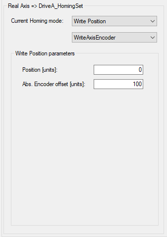
For detailed information about the parameters refer to PDL.ST_HomeWritePos. |