Motion Design Object Editor
Overview
The motion design object editor is exclusive to the M262 Motion Controller
The motion design object editor provides a generic base for configuring different motion design objects such as:
-
A real axis as, for example, the Lexium 32S servo drive.
-
A variable that implements a motion design objects interface.
To add a motion design object editor to your project, right-click the node, and execute the command . The dialog box allows you to select the type of motion design object to be created.
Adding a Motion Design Object of Type
For the = , the following elements are available in the dialog box:
|
Element |
Description |
|---|---|
|
section |
The settings you specify here can be modified in the tab of the motion design object editor. |
|
|
Click the browse button () to select one of the supported function blocks or enter it directly into the field on the left-hand side. |
|
|
Select a device object from the controller configuration that implements one of the interfaces of a motion design object, such as a Lexium 32 S standalone servo drive. |
|
|
A global variable of a motion design object interface is created. It can be accessed by IEC code by using the name of the object. |
|
button |
Click the button to:
|
Motion Design Object Editor of a Virtual Axis
The motion design object editor allows you to edit the parameter values. For the = , it provides two tabs with the following parameters.
Elements of the tab:
|
Element |
Description |
|---|---|
|
section |
The section allows you to select the graphical representation of the on the lower left side of the editor:
|
|
section |
|
|
|
Enter a value for the deceleration ramp in Units/s2. |
|
|
Enter a value for the jerk ramp in Units/s2. |
|
|
Graphical control of the position of the axis in modulo or linear mode, as defined with the parameter. |
|
|
Present state of the axis represented a a graphical chart. |
|
|
List of the components used for the virtual axis, indicating the , , and values. |
Elements of the tab:
The tab contains the and parameters that are similar to the dialog box and that can be modified here.
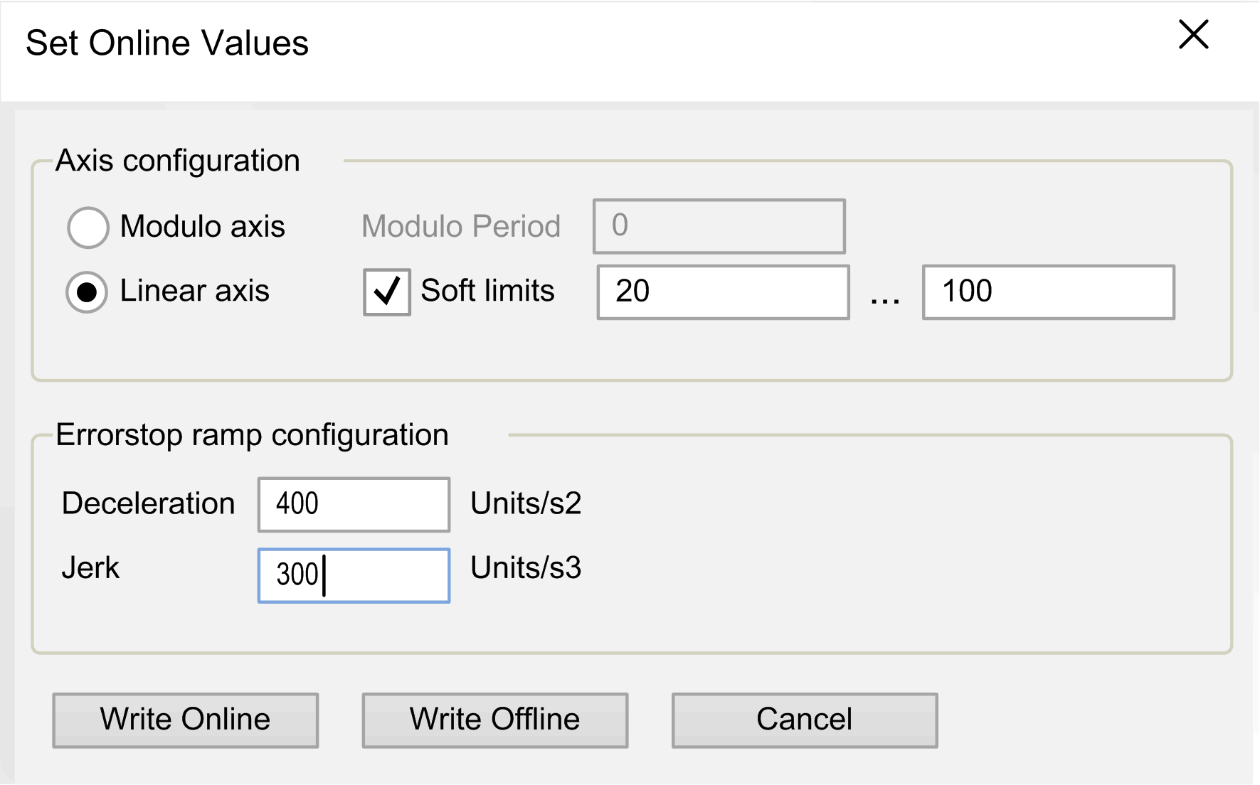
Modifying the Configuration in Online Mode
You can modify the values of the parameters if you are logged in to the controller by double-clicking an editable cell of the parameter list in the tab.
Result: The dialog box opens. It displays the configuration that is present in the controller.

You can modify the configuration according to your individual requirements.
The following options are available:
-
Click the button to write the values to the controller. If errors are detected during this operation, a message box is displayed. After the values have been successfully written to the controller, the dialog box is closed.
-
Click the button to save the values to the EcoStruxure Machine Expert project. The dialog box is closed.