SystemVoltageBasic - Functional Description
Functional Description
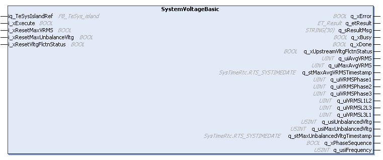
The function block SystemVoltageBasic returns and resets the voltage registers of the system avatar.
Interface
|
Input |
Data type |
Description |
|---|---|---|
|
iq_TeSysIslandRef |
FB_TeSys_island |
Reference to the TeSys island device. |
|
i_xExecute |
BOOL |
Upon a rising edge of this input, the function block starts the execution. The outputs q_xDone, q_xError, q_etResult, and q_etResultMsg are reset with the falling edge of i_xExecute. Refer to Behavior of Function Blocks with the Input i_xExecute. |
|
i_xResetMaxVRMS |
BOOL |
If this input is set to TRUE, the value of the parameter q_udiResetMaxVRMS is reset. |
|
i_xResetMaxUnbalanceVltg |
BOOL |
If this input is set to TRUE, the value of the parameter q_udiResetMaxUnbalanceVltg is reset. |
|
i_xResetVltgFlctnStatus |
BOOL |
If this input is set to TRUE, the value of the parameter q_udiResetVltgFlctnStatus is reset. |
|
Output |
Data type |
Description |
|---|---|---|
|
q_xError |
BOOL |
If this output is set to TRUE, an error has been detected. For details, refer to q_etResult and q_etResultMsg. |
|
q_etResult |
ET_Result |
Provides diagnostic and status information as a numeric value. |
|
q_sResultMsg |
STRING[30] |
Provides additional diagnostic and status information as a text message. |
|
q_xBusy |
BOOL |
If this output is set to TRUE, the function block execution is in progress. |
|
q_xDone |
BOOL |
If this output is set to TRUE, the execution has been completed successfully. |
|
q_xUpstreamVltgFlctnStatus |
BOOL |
If this output is set to TRUE, a voltage dip or swell is detected. Can be reset with i_xResetVltgFlctnStatus. |
|
q_uiAvgVRMS |
UINT |
Average RMS voltage on three phases (Unit: V). |
|
q_uiMaxAvgVRMS |
UINT |
Maximum voltage the system measured (Unit: V). |
|
q_stMaxAvgVRMSTimestamp |
SysTimeRtc.RTS_SYSTIMEDATE |
Date and time when maximum average voltage value was recorded. Refer to the SysTimeRtc library. |
|
q_uiVRMSPhase1 |
UINT |
Average RMS voltage between L1 and neutral. (Unit: V) |
|
q_uiVRMSPhase2 |
UINT |
Average RMS voltage between L2 and neutral. (Unit: V) |
|
q_uiVRMSPhase3 |
UINT |
Average RMS voltage between L3 and neutral. (Unit: V) |
|
q_uiVRMSL1L2 |
UINT |
Average RMS voltage between L1 and L2 (V). |
|
q_uiVRMSL2L3 |
UINT |
Average RMS voltage between L2 and L3 (V). |
|
q_uiVRMSL3L1 |
UINT |
Average RMS voltage between L3 and L1 (V). |
|
q_usiUnbalancedVltg |
USINT |
Unbalance voltage in percent (%). |
|
q_usiMaxUnbalancedVltg |
USINT |
Maximum unbalance voltage in percent (%). |
|
q_stMaxUnbalancedVltgTimestamp |
SysTimeRtc.RTS_SYSTIMEDATE |
Date and time of maximum unbalance voltage. Refer to the SysTimeRtc library. |
|
q_xPhaseSequence |
BOOL |
If this output is set to TRUE, the phase order is ACB (FALSE = phase order ABC). |
|
q_usiFrequency |
USINT |
Main power voltage frequency (line frequency as measured on phase 1). (Unit: Hertz) |