Legend of State Machine Diagrams
State machine diagrams are provided in this library guide for each function block to illustrate the specific behavior. The following table lists the symbols of state machine diagrams with a short description.
|
Symbol |
Description |
|---|---|
|
Black line |
Functional procedure |
|
Green line |
|
|
Red line |
Detected error-related procedure |
|
Blue line |
Abort procedure |
|
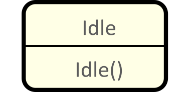
Idle state (waiting for an input command). |

|
Setting the value of an input variable. The colors of the frames correspond to the procedure type (see lines 1...4 of this table). |
|
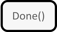
Simple method, called once when a state transitions is performed. |
|
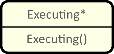
State of the internal state machine, a specific control method is called. |
|
|
Return value of the specific control method (type ET_Result). |