ST_TemperatureControl
Description
The structure ST_TemperatureControl provides various parameters needed for the temperature control function block (FB_HeatingControl).
Structure Elements
|
Name |
Data type |
Description |
|---|---|---|
|
rSetPointHighLimit |
REAL |
High limit for set point. Also refer to rSetPointHighLimit, rSetPointLowLimit. Range: -100000 < rSetPointHighLimit ≤ 100000 [user-defined temperature unit] rSetPointHighLimit > rSetPointLowLimit Default value: 100
NOTE: Adjust the set point range to the requirements of the heating system and the working range of your application.
|
|
rSetPointLowLimit |
REAL |
Low limit for set point. Also refer to rSetPointHighLimit, rSetPointLowLimit. Range: -100000 ≤ rSetPointLowLimit < 100000 [user-defined temperature unit] rSetPointLowLimit < rSetPointHighLimit Default value: 0
NOTE: Adjust the set point range to the requirements of the heating system and the working range of your application.
|
|
rPidHighLimit |
REAL |
High limit for the internal PID controller output. Also refer to rPidLowLimit, rPidHighLimit. Range: Heating: rPidLowLimit < rPidHighLimit ≤ 100 % Default value: 100 % |
|
rPidLowLimit |
REAL |
Low limit for the internal PID controller output. Also refer to rPidLowLimit, rPidHighLimit. Range: 0 % ≤ rPidLowLimit < rPidHighLimit Default value: 0 % |
|
rPwmTimePeriod |
REAL |
Time period for the PWM (Pulse-Width Modulation) signal in [s]. Also refer to rPwmTimePeriod. This value scales the output q_rAnalogOutput to the PWM output q_xPwmOutput. Range: 0.1...60 s Default value: 10 s
NOTE: The least value that can be set depends on the cycle time with which the function block is called. The value of rPwmTimePeriod must be greater than the cycle time by at least the factor uiPwmCycleTimeToTaskRatio. For example, with a determined cycle time of 50 ms and a uiPwmCycleTimeToTaskRatio of 10, a value range of 0.5 s...60 s is allowed.
The accuracy of the PWM output q_xPwmOutput on-time related to rPwmTimePeriod to the analog value q_rAnalogOutput depends both on the cycle time of the task as well as on the rPwmTimePeriod. q_xPwmOutput can be switched on/off with each task cycle. Thus, the total ratio of (q_xPwmOutput on-time / rPwmTimePeriod) is closer to the q_rAnalogOutput value the less the cycle time of the task and the greater the value of rPwmTimePeriod. On the other hand, with the same q_rAnalogOutput value, the q_xPwmOutput Boolean value is TRUE for a longer time the greater the value of rPwmTimePeriod. Example: If q_rAnalogOutput = 50 % => On / off-time of q_xPwmOutput = 5 s if rPwmTimePeriod = 10 s |
|
rDigitalFilterTime |
REAL |
Filter time of the digital filter (noise reduction) in [ms]. Also refer to rDigitalFilterTime. If no value is given, the filter is not activated. A value less than the (determined) cycle time is not allowed. Range: 0...100000 ms Default value: 0 ms |
|
rDeadBand |
REAL |
Dead band for the internal calculation of the control deviation. If the absolute value of the control deviation is smaller than the dead band, the control deviation is set to zero. Also refer to rDeadBand. Range: 0...100 [user-defined temperature unit] Default value: 0 [user-defined temperature unit]
NOTE: Any dead band value greater than 0 negatively influences the precision of temperature control.
|
|
rAutoTuneHysteresis |
REAL |
Hysteresis value [% of user-defined temperature unit] for switching the heating on and off during auto-tuning is active. Refer to Hysteresis During Auto-tuning. Range: 0.1…0.5 % Default value: 0.2 % |
|
uiPwmCycleTimeToTaskRatio |
UINT |
Specifies the minimum ratio of the task cycle time to rPwmTimePeriod. If the ratio is less than 1 or greater than 100, a diagnostic message is issued. Range: 1…100 Default value: 1
NOTE: The accuracy of the PWM mark-to-space ratio is greater the greater the set PWM time is in relation to the determined cycle time.
|
rPidLowLimit, rPidHighLimit
The values at these pins define the range of PID output. These values are configured as per the analog output module specification. The range is 0...100 %.
rPwmTimePeriod
Example:
rPwmTimePeriod := 10 s, rPidHighLimit := 100 %, rPidLowLimit: = 0 %, q_rAnalogOutput := 10.95 %
-
PWM time on := 1,095 s
-
PWM time off := 8,905 s
rSetPointHighLimit, rSetPointLowLimit
These values determine the range of i_rSetpoint. These values are decided with the minimum and maximum temperature which can be applied to the process so that it stops the temperature from increasing or decreasing then the desired limits.
rDigitalFilterTime
If you get a noisy signal of the process value, you have to set the digital filter time. The filter is active when the digital filter time is greater than 0 ms. When the digital filter time is set, you get the medium process value for the entered digital filter time.
PWM Working Principles
Pulse-width modulation (PWM) in this case is a method of controlling the average power delivered by the analog PID controller output signal. The average value provided to the load is controlled by switching the power supply of a heating system between 0 and 100% at a rate faster than it takes the load to change significantly. The longer the switch is on, the higher the total power supplied to the load.
Consider the following while determining the value for rPwmTimePeriod:
-
A value that is too great for the application can lead to oscillations in the load.
-
An insufficient value can lead to premature wear of the mechanical control components, for example, when using a mechanical relay.
-
Consider the given task cycle time: an insufficient rPwmTimePeriod to task cycle time ratio can have the effect that analog values are not displayed correctly.
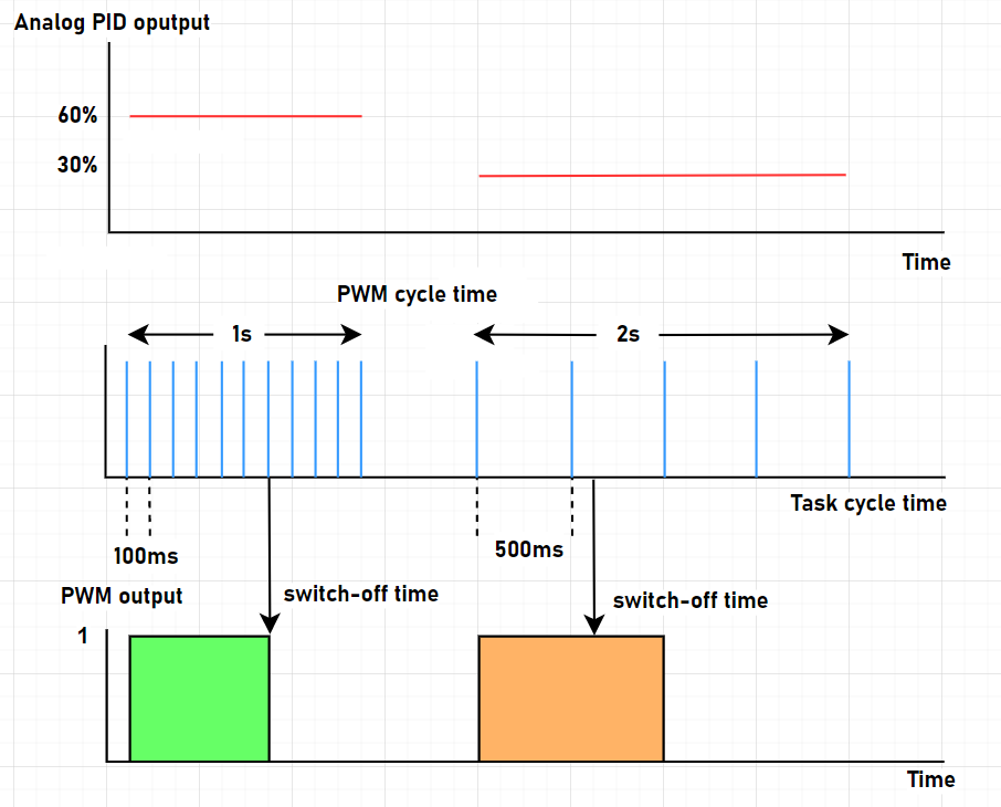
The orange example in the figure indicates an analog value of 30 % which results in a duty cycle of 666 ms on. Since the internal timer is evaluated every 500 ms, this duty cycle cannot be achieved. A total duty cycle of 1000 ms is provided instead which provides 50% analog value instead of the required 30% and, thus, provides more energy than required to the system. This can lead to a greater temperature control deviation around the set point value.
You can compensate for this over time issue by appropriate calculations. In principle, select a value for rPwmTimePeriod that is significantly greater than the task cycle time. You can configure the minimum ratio (distance) by the factor uiPwmCycleTimeToTaskRatio.